Check patentability & draft patents in minutes with Patsnap Eureka AI!

Rotor, permanent magnet synchronous motor and manufacturing method of rotor

A manufacturing method and rotor technology are applied in the field of permanent magnet synchronous motor, rotor manufacturing, and rotor, which can solve the problems of difficult actual production and difficult stator insert production, and achieve the effect of reducing cogging torque and optimizing magnetic field distribution.

Pending Publication Date: 2021-03-09
WUHAN HUADA NEW TYPE MOTOR CO LTD
View PDF0 Cites 0 Cited by
  • Summary
  • Abstract
  • Description
  • Claims
  • Application Information

AI Technical Summary

Problems solved by technology

However, the structure of the helical keyway stator causes relatively great difficulties in the production of stator inlaid wires, and is difficult to be used in actual production

Method used


Image

  • Rotor, permanent magnet synchronous motor and manufacturing method of rotor
  • Rotor, permanent magnet synchronous motor and manufacturing method of rotor
  • Rotor, permanent magnet synchronous motor and manufacturing method of rotor

Examples


Embodiment 1

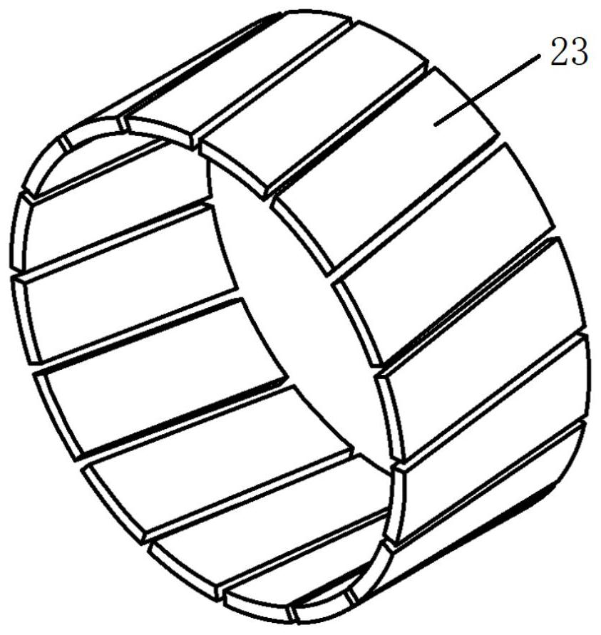
[0054] as attached figure 1 As shown, it is a rotor provided by an embodiment of the present invention, and the rotor includes:

[0055] Spindle 1;

[0056] The first rotor core part 2; a plurality of first rotor slots 3 spiraling along the first direction are evenly distributed in the circumferential direction of the first rotor core part 2;

[0057] The second rotor core part 4; the circumferential direction of the second rotor core part 4 is uniformly distributed with a plurality of second rotor slots 5 spiraling along the second direction; the second rotor slots 5 are connected with the first rotor The groove 3 communicates; the second direction is opposite to the first direction.

[0058] In this embodiment, both the first rotor core part 2 and the second rotor core part 4 are fixed on the rotating shaft 1 . Since the helical directions of the first rotor slot 3 and the second rotor slot 5 are opposite and the first rotor slot 3 and the second rotor slot 5 are arranged s...

Embodiment 2

[0072] An embodiment of the present invention also provides a permanent magnet synchronous motor, which includes: a motor housing, a stator, and the rotor described in any one of Embodiment 1.

[0073] In this embodiment, a permanent magnet synchronous motor is prepared by using the motor housing, the stator, and the rotor in the first embodiment, and the permanent magnet synchronous motor has all the advantages of the rotor in the first embodiment.

Embodiment 3

[0075] An embodiment of the present invention also provides a rotor manufacturing method, including the processing technology of the rotating shaft 1, the processing technology of the rotor core, the processing technology of the magnetic steel sheet and the assembly technology of the rotor.

[0076] As a preferred embodiment of the present invention, the processing technology of the rotating shaft 1 includes:

[0077] The OEM workpiece is clamped on the worktable of the vertical machining center with X-axis rotation function by clamping at one end and thimble at the other end;

[0078] The vertical milling cutter is used to process the OEM workpiece; the diameter of the vertical milling cutter is selected according to the width of the rotor groove on the rotor, so as to ensure that the width of the rotor groove and the tooth width of the rotor punch are transitionally matched; the spindle of the vertical machining center The speed is 1500rpm-2000rpm, and the axial feed speed i...


PUM


Abstract

The invention is applicable to the technical field of motors, and provides a rotor, a permanent magnet synchronous motor and a manufacturing method of the rotor. The rotor includes a rotating shaft, afirst rotor core part, wherein a plurality of first rotor grooves which are spiral along a first direction are uniformly distributed in the circumferential direction of the first rotor core part, a second rotor core part, wherein a plurality of second rotor grooves which are spiral along a second direction are uniformly distributed in the circumferential direction of the second rotor core part, the second direction is opposite to the first direction, and the second rotor grooves and the first rotor grooves are symmetrical about the contact surface of the first rotor core part and the second rotor core part. According to the invention, the magnetic field distribution is optimized to a great extent, and the cogging torque is reduced; the unbalance amount cannot be generated structurally, and the dynamic balance of the rotor is easier to realize; and the first rotor core part and the second rotor core part are easy to distinguish, and errors do not occur in the rotor assembling process.

Description

technical field [0001] The invention belongs to the technical field of motors, and in particular relates to a rotor, a permanent magnet synchronous motor and a method for manufacturing the rotor. Background technique [0002] Due to its high torque, high power density and wide speed expansion range, permanent magnet synchronous motors are widely used in hybrid vehicles (such as Toyota Prius) and new energy electric vehicles. Compared with the surface-mounted permanent magnet synchronous motor with the same air gap length, the existence of the reluctance torque will produce larger torque ripple, and there are more parameters to be adjusted to reduce the torque ripple. High torque ripple will affect the control accuracy of the servo system and cause the vibration of the motor and shorten the life of the motor. Therefore, it is a key issue to design the internal permanent magnet synchronous motor to output a small ripple torque. [0003] Generally, pulsating torque (Pulsating ...

Claims


Application Information

Patent Timeline
Patent Type & Authority Applications(China)
IPC IPC(8): H02K1/27H02K21/02H02K15/03
CPCH02K1/278H02K15/03H02K21/02
Inventor 汤欢杜成飞肖杨宋宝王坤陈彪付静静程佳董坤
Owner WUHAN HUADA NEW TYPE MOTOR CO LTD
Features
  • R&D
  • Intellectual Property
  • Life Sciences
  • Materials
  • Tech Scout
  • Unparalleled Data Quality
  • Higher Quality Content
  • 60% Fewer Hallucinations
Learn More