
Multifunctional low-pressure industrial waste gas burner
An industrial waste gas, multi-functional technology, applied in the direction of combustion method, combustion type, lighting and heating equipment, etc., can solve the problems of inconvenient observation, inconvenient cleaning of the inner wall of the equipment, inconvenient equipment maintenance, etc., to increase the observation function. Effect
- Summary
- Abstract
- Description
- Claims
- Application Information
AI Technical Summary
Problems solved by technology
Method used
Image

Examples
Embodiment Construction
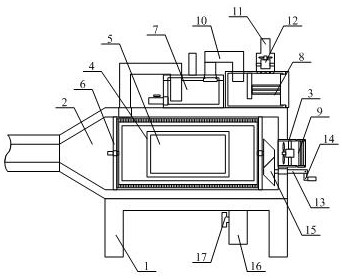
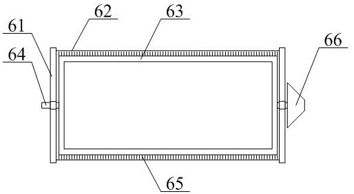
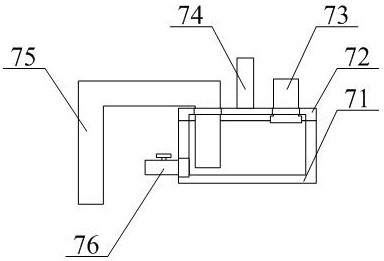
[0035] The present invention is described in detail below in conjunction with accompanying drawing, as appended figure 1 And attached figure 2 As shown, a multifunctional low-pressure industrial waste gas burner includes a support frame 1, a fixed shell 2, a first connecting pipe 3, a fixed frame 4, an observation piece 5, a structure that can support a rotary cleaning furnace 6, and a structure that can replace a purification box 7. Detachable maintenance discharge box structure 8, heatable and detachable air inlet pipe structure 9, guide pipe 10, inverted T-shaped discharge pipe 11, first fan assembly 12, rotating rod 13, hand lever 14, first cone Gear 15, impurity discharge pipe 16 and discharge valve 17, the upper end of the support frame 1 is bolted to the lower right side of the fixed shell 2; the first connecting pipe 3 is threaded to the middle of the right side of the fixed shell 2 position; the fixed frame 4 is bolted to the middle of the front surface of the fixed...
PUM
 Abstract
Description
Claims
Application Information