Double-fundamental-frequency three-channel time-base control circuit of through-wall imaging radar
A timing control circuit and imaging radar technology, applied in the field of radar, can solve problems such as the inability to obtain detection data and the bottleneck of sampling frequency accuracy, and achieve the effects of improving signal-to-noise ratio, high-precision time base control, and improving stability
- Summary
- Abstract
- Description
- Claims
- Application Information
AI Technical Summary
Problems solved by technology
Method used
Image

Examples
Embodiment Construction
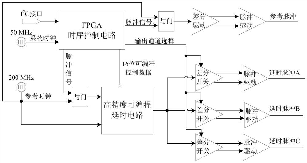
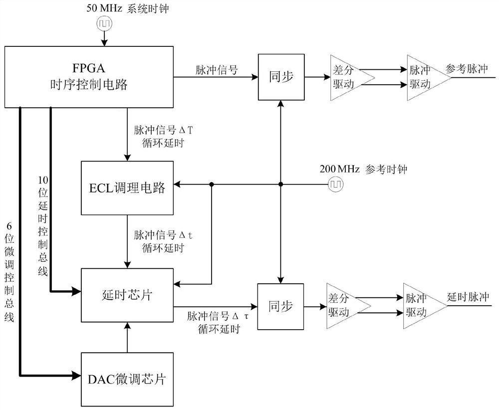
[0029] Such as figure 1 with figure 2 As shown, a through-wall imaging radar dual-base frequency three-channel time-base control circuit includes an FPGA timing control circuit, a programmable timing control circuit, a system clock circuit, a reference clock circuit and a delay pulse output circuit arranged in parallel with three routes;
[0030] The FPGA timing control circuit includes an FPGA module, which is electrically connected to the system clock circuit. The FPGA module communicates with the host computer through the I2C interface, and receives various time base control parameters from the host computer, including the delay configuration register control word, time window Range control word, channel switching frequency control word, etc., and store the parameter data, FPGA configures the working mode of the time base control circuit according to the command parameters, thus determining the working mode of the through-wall imaging radar.
[0031] FPGA modules include:...
PUM
 Abstract
Description
Claims
Application Information
 - R&D Engineer
- R&D Manager
- IP Professional
- Industry Leading Data Capabilities
- Powerful AI technology
- Patent DNA Extraction
Browse by: Latest US Patents, China's latest patents, Technical Efficacy Thesaurus, Application Domain, Technology Topic.
© 2024 PatSnap. All rights reserved.Legal|Privacy policy|Modern Slavery Act Transparency Statement|Sitemap