Eureka AIR delivers breakthrough ideas for toughest innovation challenges, trusted by R&D personnel around the world.

High-precision and high-thermal-stability optical splicing focal plane applied to space camera

A high thermal stability, optical splicing technology, applied in the field of space optical remote sensing, can solve problems such as unfavorable image synthesis, dark current noise increase, thermal expansion deformation of structural parts, etc., to reduce the temperature fluctuation range, reduce dark current noise, Relieve the effect of overheating

Active Publication Date: 2021-03-12
CHANGGUANG SATELLITE TECH CO LTD
View PDF8 Cites 3 Cited by
  • Summary
  • Abstract
  • Description
  • Claims
  • Application Information

AI Technical Summary

Problems solved by technology

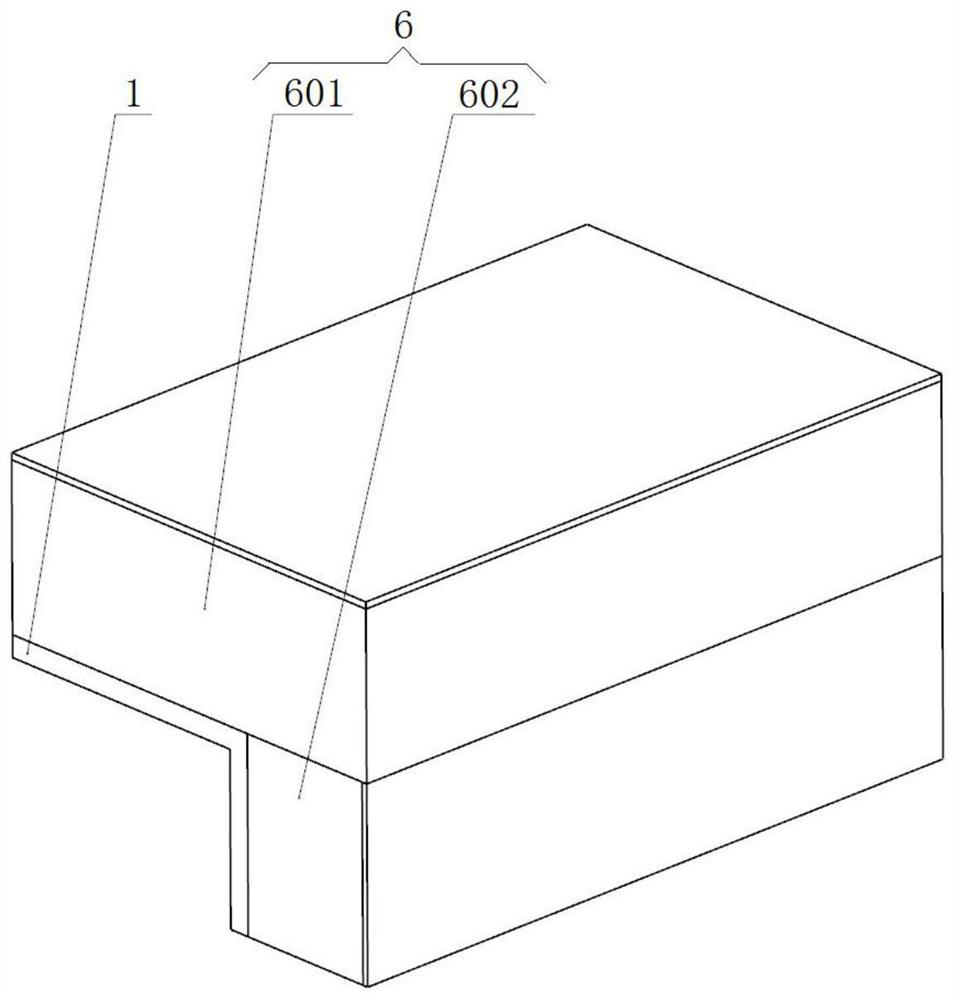
[0004] Although the splicing of multiple image sensors can meet the requirements of large field of view and high resolution, the simultaneous operation of multiple sensors will generate a lot of heat, which will cause the temperature of the focal plane to rise and make the dark current noise of each image sensor become larger, resulting in a decline in the imaging quality of each sensor, and the thermal expansion and deformation of structural parts caused by excessive temperature changes, resulting in poor stitching accuracy of the focal plane, which is not conducive to image synthesis. Therefore, it is urgent to provide a space camera. High precision, high thermal stability optical splicing focal plane

Method used


Image

  • High-precision and high-thermal-stability optical splicing focal plane applied to space camera
  • High-precision and high-thermal-stability optical splicing focal plane applied to space camera
  • High-precision and high-thermal-stability optical splicing focal plane applied to space camera

Examples


Embodiment Construction

[0051] In order to enable those skilled in the art to better understand the technical solutions of the present invention, the present invention will be further described in detail below in conjunction with the accompanying drawings.

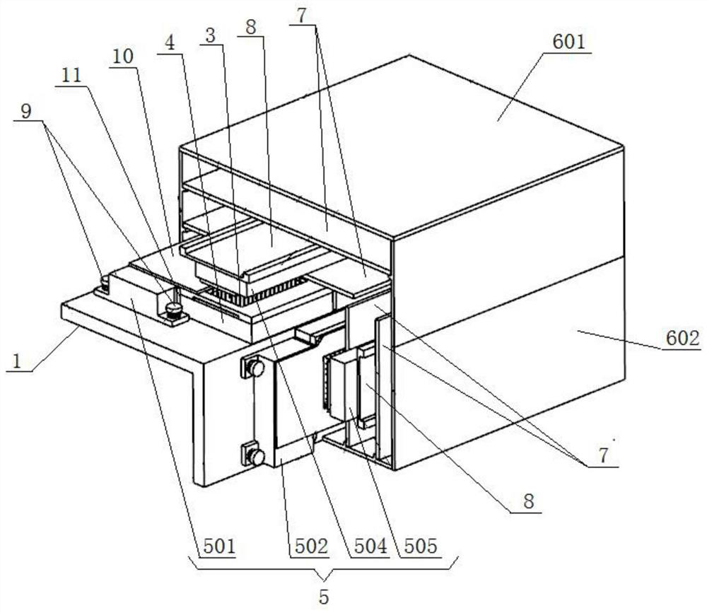
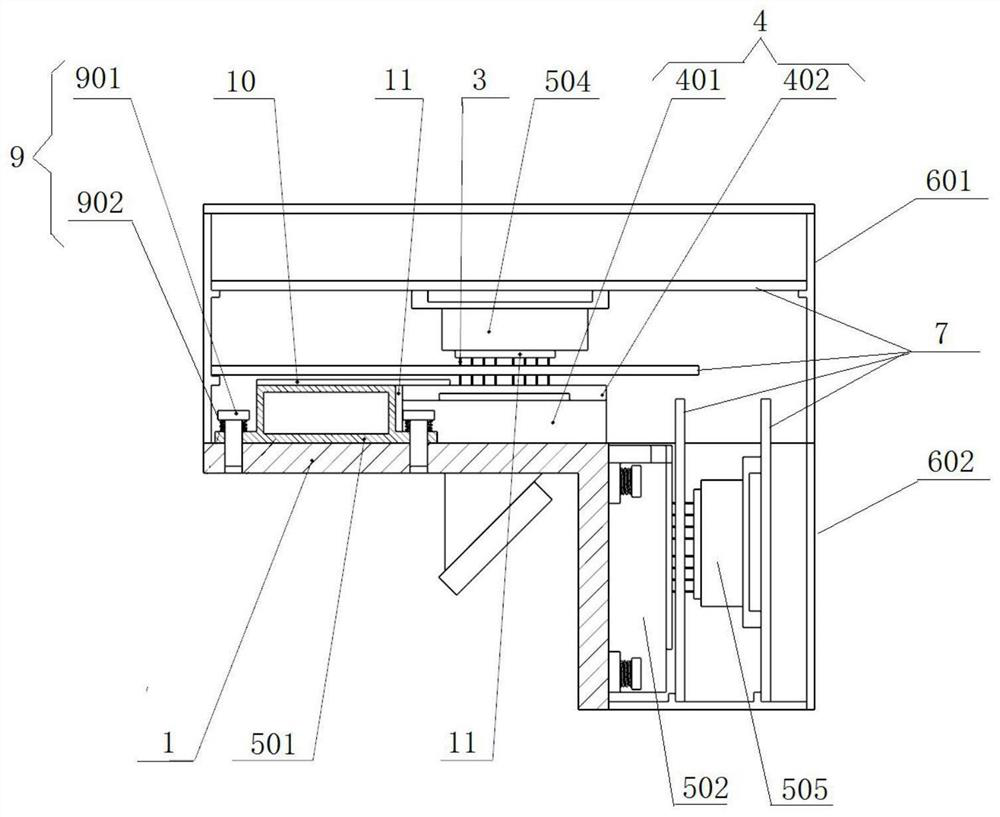
[0052] see Figure 1-6 shown;

[0053] Invented a high-precision, high-thermal-stability optical stitching focal plane applied to space cameras, including:

[0054] A substrate 1, a plurality of beam splitter assemblies 2 are installed on one side, and a plurality of image sensors 3 are installed on the other side through a holder assembly 4;

[0055] A box body 6, which is covered outside the image sensor 3, and the box body 6 is fixedly connected to the substrate 1;

[0056] A phase-change energy storage box group 5, which includes a first phase-change energy storage box group installed on the substrate 1 and a second phase-change energy storage box group installed on the box body 6;

[0057] The first phase change energy storage box group i...


PUM


Abstract

The invention discloses a high-precision and high-thermal-stability optical splicing focal plane applied to a space camera, belongs to the technical field of space optical remote sensing, and aims tosolve the technical problem of poor imaging quality of a plurality of sensors due to temperature rise of a focal plane in the prior art. The optical splicing focal plane is characterized in that: a substrate is arranged, one side of the substrate is provided with multiple spectroscope assemblies, a plurality of image sensors are mounted on the other side through a fixed seat assembly; a box body covers the image sensor; the phase change energy storage box group comprises a first phase change energy storage box group arranged on the substrate and a second phase change energy storage box group arranged on the box body; the first phase change energy storage box group is in contact with the fixed seat assembly through the heat conduction pad; the second phase change energy storage box group isin contact with the image sensor through the heat conduction pad, wherein a plurality of layers of heat conduction films are laid on the upper surfaces of the first phase change energy storage box set and the fixing base assembly and used for communicating the upper surfaces of the first phase change energy storage box set and the fixing base assembly, and the device has the beneficial effects ofbeing high in precision, high in thermal stability and capable of improving the imaging quality.

Description

technical field [0001] The invention relates to the technical field of space optical remote sensing, in particular to a high-precision, high-thermal-stability optical splicing focal plane applied to a space camera. Background technique [0002] With the continuous development of optical remote sensing technology, the field of view of space cameras is increasing, and the imaging resolution is increasing, which requires image sensors to have more pixels. However, due to the constraints of manufacturing processes and technical conditions, the image sensor The size cannot be very large, and a single-chip image sensor can no longer meet the requirements of use, and multiple pieces need to be spliced ​​to form an equivalent large-size focal plane; [0003] The optical splicing scheme is a kind of splicing method of multi-chip image sensors, which has the advantages of simultaneous imaging and high energy utilization rate. The surface is used to arrange multiple image sensors, and...

Claims


Application Information

Patent Timeline
IPC IPC(8): H04N5/225H04N5/361G03B17/55
CPCG03B17/55H04N23/55H04N23/54H04N25/63
Inventor 王平李季张雷贾学志周楠
Owner CHANGGUANG SATELLITE TECH CO LTD
Why Eureka
Eureka Blog
Learn More