Cast-in-place box girder spanning cavern method for karst tunnel

A cast-in-place and tunnel technology, which is applied in bridges, bridge construction, erection/assembly of bridges, etc., can solve problems such as difficulty in determining the position of the crack tip by the crack stop method, reduction of structural rigidity and ultimate bearing capacity, and damage to diaphragms

Pending Publication Date: 2021-03-16
中铁二十局集团第三工程有限公司
View PDF2 Cites 3 Cited by
  • Summary
  • Abstract
  • Description
  • Claims
  • Application Information

AI Technical Summary

Problems solved by technology

[0004] (1) In the traditional box girder reinforcement method, there are problems such as the difficulty in determining the position of the crack tip in the crack arrest hole method, and the cracks can continue to develop through the crack arrest hole.
[0005] (2) The crack filling method has high requirements on the performance of the filling material and construction technology, and the crack arrest effect varies.
[0006] (3) The improved geometric shape method may reduce the stiffness and ultimate bearing capacity of the structure, which is not applicable to long cracks
[0007] (4) Bolt holes added by the bolted steel plate method will cause new damage to the diaphragm, and the added weight will be large. It is difficult to evaluate the effect of improving the crack tip stress. It is necessary to formulate reinforcement schemes for different crack directions one by one, giving design and construction bring great difficulty
[0008] (5) The newly developed UHPC method has little improvement in the stress range of the parent material of the transverse diaphragm at the arc-shaped cut away from the bridge deck, and the cost is high
[0009] The difficulty of solving the above problems and defects is: the above problems are difficult to deal with, difficult to cure, and affect the appearance

Method used


Image

  • Cast-in-place box girder spanning cavern method for karst tunnel
  • Cast-in-place box girder spanning cavern method for karst tunnel
  • Cast-in-place box girder spanning cavern method for karst tunnel

Examples


Embodiment Construction

[0255] In order to make the object, technical solution and advantages of the present invention more clear, the present invention will be further described in detail below in conjunction with the examples. It should be understood that the specific embodiments described here are only used to explain the present invention, not to limit the present invention.

[0256] Aiming at the problems existing in the prior art, the present invention provides a method for crossing the karst box girder in the karst tunnel. When crossing the karst cavity, the box girder is used for crossing, and the second lining is placed on the joist, so that ballastless The track and the secondary lining structure are separated by force, and the dynamic and static structures span, which not only ensures the stability of the secondary lining but also ensures the safety of later operation. The invention will be described in detail below in conjunction with the accompanying drawings.

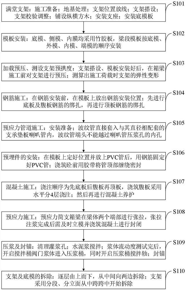
[0257] Such as figure 1 ...


PUM


Abstract

The invention belongs to the technical field of box girder spanning cavern construction, and discloses a cast-in-place box girder spanning cavern method for a karst tunnel, which comprises the following steps of treating a foundation; erecting a bracket; mounting an outer side mold; binding bottom and web steel bars; threading the steel strands; mounting an inner mold; binding top plate reinforcing steel bars; pouring concrete; carrying out surface finishing and maintenance; conducting pre-tensioning and initial tensioning; removing the template and the bracket; performing final tensioning andmud jacking; adopting a full framing method for construction; the bottom die, the outer die and the inner die are all wood dies, the inner supports are pulled outwards, and tie bars are arranged at the beam bottom and the beam top for reinforcement; concrete pouring adopts centralized stirring of a mixing station, a tank truck transports the concrete to a construction site, and a delivery pump truck pours the concrete; the full framing foundation is locally filled with tunnel hole slag, a water passing channel is reserved, and the foundation is hardened by C20 concrete by 30 cm. The method isconvenient to construct, durable, convenient to maintain, small in investment scale, good in universality and high in economic benefit; obvious stress concentration cannot be generated at the periphery, and a new fatigue risk source is prevented from being introduced.

Description

technical field [0001] The invention belongs to the technical field of construction of a box girder spanning a dissolved cavity, and in particular relates to a method for a cast-in-situ box girder spanning a dissolved cavity in a karst tunnel. Background technique [0002] At present, box girders are widely used in the construction of large and medium-sized bridges. The structure of box girders includes diaphragms arranged at intervals, top plates, bottom plates, vertical stiffeners arranged perpendicular to The notch, the U rib fixed in the notch. However, the fatigue problem of box girder is a big problem in bridge engineering field. Traditional box girder strengthening methods include: crack hole method, crack filling method, improved geometry method, and bolted steel plate method, etc. The crack stop method has problems such as difficulty in determining the position of the tip of the crack, and the crack can continue to develop through the stop hole. The crack filling...

Claims


Application Information

Patent Timeline
Patent Type & Authority Applications(China)
IPC IPC(8): E01D21/00E01D2/04
CPCE01D21/00E01D2/04
Inventor 朱清利任高峰朱朋刚王锋张秦军郭凯吕增寅唐辉张军
Owner 中铁二十局集团第三工程有限公司
Why Eureka
Try Eureka