
Groove type capacitor device and preparation method

A trench capacitor and trench technology, applied in the field of semiconductor passive device manufacturing, can solve the problems of BARC residue, plasma damage, difficulty in BARC and photoresist removal, etc.

Inactive Publication Date: 2021-03-16
SHANGHAI INTEGRATED CIRCUIT EQUIP & MATERIALS IND INNOVATION CENT CO +2
View PDF5 Cites 0 Cited by
  • Summary
  • Abstract
  • Description
  • Claims
  • Application Information

AI Technical Summary

Problems solved by technology

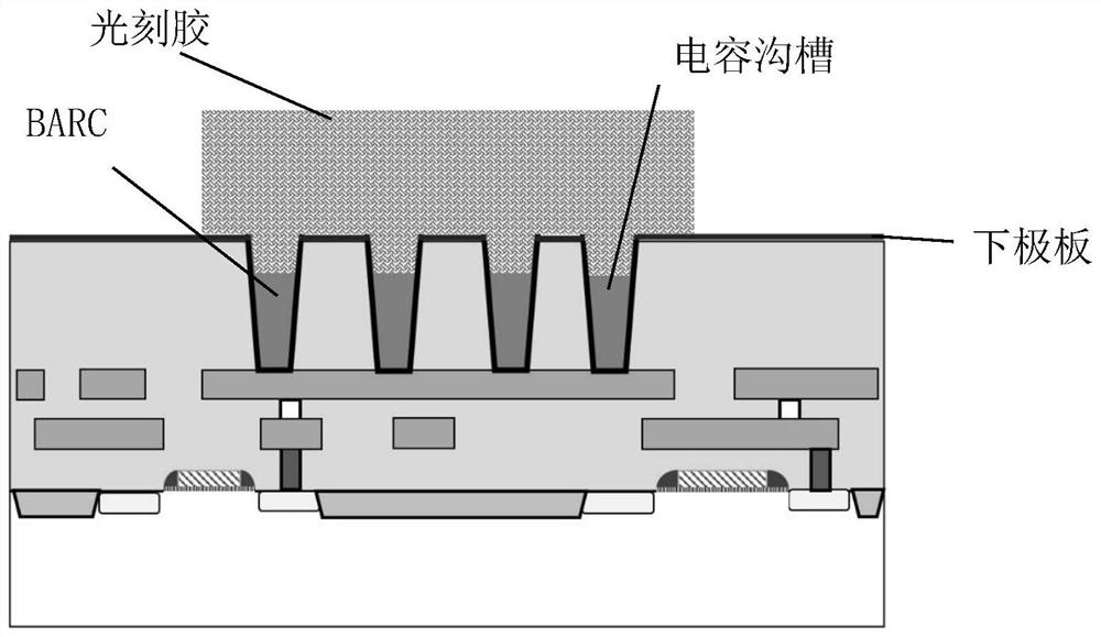
[0003] figure 2 Shown is the cross-sectional view of the trench capacitor device in the prior art after the photolithography of the lower electrode layer is completed. Usually, the dry or wet stripping process is used to remove the BARC and photoresist filled in the trench, and the dry process is used. During the process, the plasma is easy to cause plasma damage to the lower electrode layer
In addition, in order to increase the capacitance per unit area, the trench opening is reduced while increasing the depth of the trench capacitor device, thus making it difficult to remove the BARC and photoresist in the trench, and it is easy to form BARC residues and Photoresist residue, which ultimately affects the reliability and yield of trench capacitor devices

Method used


Image

  • Groove type capacitor device and preparation method
  • Groove type capacitor device and preparation method
  • Groove type capacitor device and preparation method

Examples


Embodiment Construction

[0038] In order to make the contents of the present invention, the contents of the present invention will be further described below with reference to the accompanying drawings. Of course, the present invention is not limited to this particular embodiment, and general alternatives well known to those skilled in the art are also included within the scope of the invention.

[0039] It should be noted that in the following detailed description of the embodiments of the present invention, in detail to clearly represent the structure of the present invention to facilitate explanation, the structure in the drawings is not in accordance with general proportional drawings, and The local amplification, deformed, and simplified processing should therefore be avoided as limiting the invention.

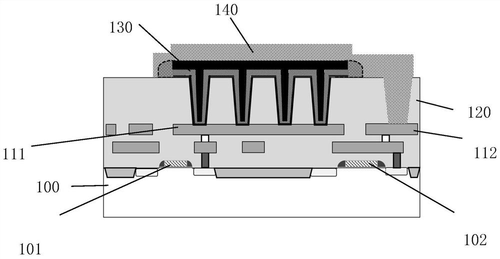
[0040] In the specific embodiments of the invention, please image 3 , image 3 It is a schematic structural diagram of a trench type capacitor device according to a preferred embodiment of the prese...


PUM


Abstract

The invention provides a groove type capacitor device and a preparation method. A groove capacitor structure of the groove type capacitor device is located at one side, far away from a substrate, of agroove dielectric layer, a first groove penetrating through the groove dielectric layer is filled, the groove capacitor structure is electrically connected with a first metal interconnection layer, acapacitor side wall covers the side surface of the groove capacitor structure, and an electrode interconnection layer fills a second trench penetrating through the trench dielectric layer and is electrically connected with the second metal interconnection layer. The capacitor side wall avoids the short circuit of an upper electrode layer and a lower electrode layer of the trench capacitor structure, achieves the purpose of improving the performance and reliability of a device, and has remarkable significance.

Description

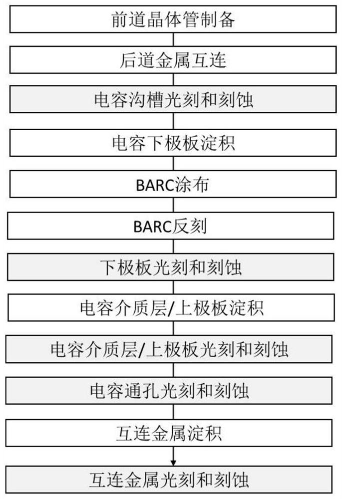
Technical field [0001] The present invention relates to the field of semiconductor passive device manufacturing, and more particularly to a trench capacitive device and a preparation method. Background technique [0002] The capacitor is a passive device for energy storage, which is widely used in semiconductor circuits such as coupling, filtering, resonance, integration, and compensation. The prior art trench capacitive device is photolithography than flat plate capacitance, which has caused the rise in manufacturing process. figure 1 For the process flow of the prior art trench capacitive device, including capacitive trench photolithography, lower plate photolithography, trench dielectric layer / upper plate photolithography, capacitive vias light engraving, and interconnect 5 lithography. Moreover, before the lower plate lithography, the coating and reaction of the bottom anti-reflective layer (BARC) can be performed in the capacitor trench, i.e., after the planarization is c...

Claims


Application Information

Patent Timeline
IPC IPC(8): H01L23/522
CPCH01L23/5223
Inventor 顾学强葛星晨范春晖
Owner SHANGHAI INTEGRATED CIRCUIT EQUIP & MATERIALS IND INNOVATION CENT CO
Learn More