
Method of forming bit line of semiconductor device

a technology of semiconductor devices and bit lines, which is applied in the direction of semiconductor devices, basic electric elements, electrical equipment, etc., can solve the problems of reducing the device operation speed more noticeably, the rc delay of capacitor coupling between adjacent conductive components becoming a serious concern, etc., and achieves the effect of preventing the capacitance increase associated with the barrier metal layer, reducing the resistance of the contact plug, and increasing the resistance of the bit lin

Inactive Publication Date: 2007-01-11
SK HYNIX INC
View PDF10 Cites 0 Cited by
  • Summary
  • Abstract
  • Description
  • Claims
  • Application Information

AI Technical Summary

Benefits of technology

The present invention provides a method for manufacturing a semiconductor device with a decreased resistance in a contact plug, via plug, or conductive line. The method includes steps of etching a first conductive layer in a contact hole, forming an interface metal layer on the etched first conductive layer, and then forming a second conductive layer. This method prevents an increase in resistance and capacitance associated with the barrier metal layer and simplifies the process, improving the reliability of cells. Additionally, the invention provides a method of forming a bit line by simultaneously forming a contact hole and the bit line, thereby preventing plasma damage and improving the reliability of cells. The invention also provides a semiconductor device with a decreased resistance in a contact plug, via plug, or conductive line.

Problems solved by technology

As the semiconductor device shrink in size, the RC delay from capacitor coupling between adjacent conductive components are becoming a more serious concern.
Accordingly, the RC delay from the coupling capacitance of these conductive lines reduces the device operational speed more noticeably.

Method used


Image

  • Method of forming bit line of semiconductor device
  • Method of forming bit line of semiconductor device
  • Method of forming bit line of semiconductor device

Examples


Embodiment Construction

[0015] The present invention will be described in detail in connection with certain embodiments with reference to the accompanying drawings.

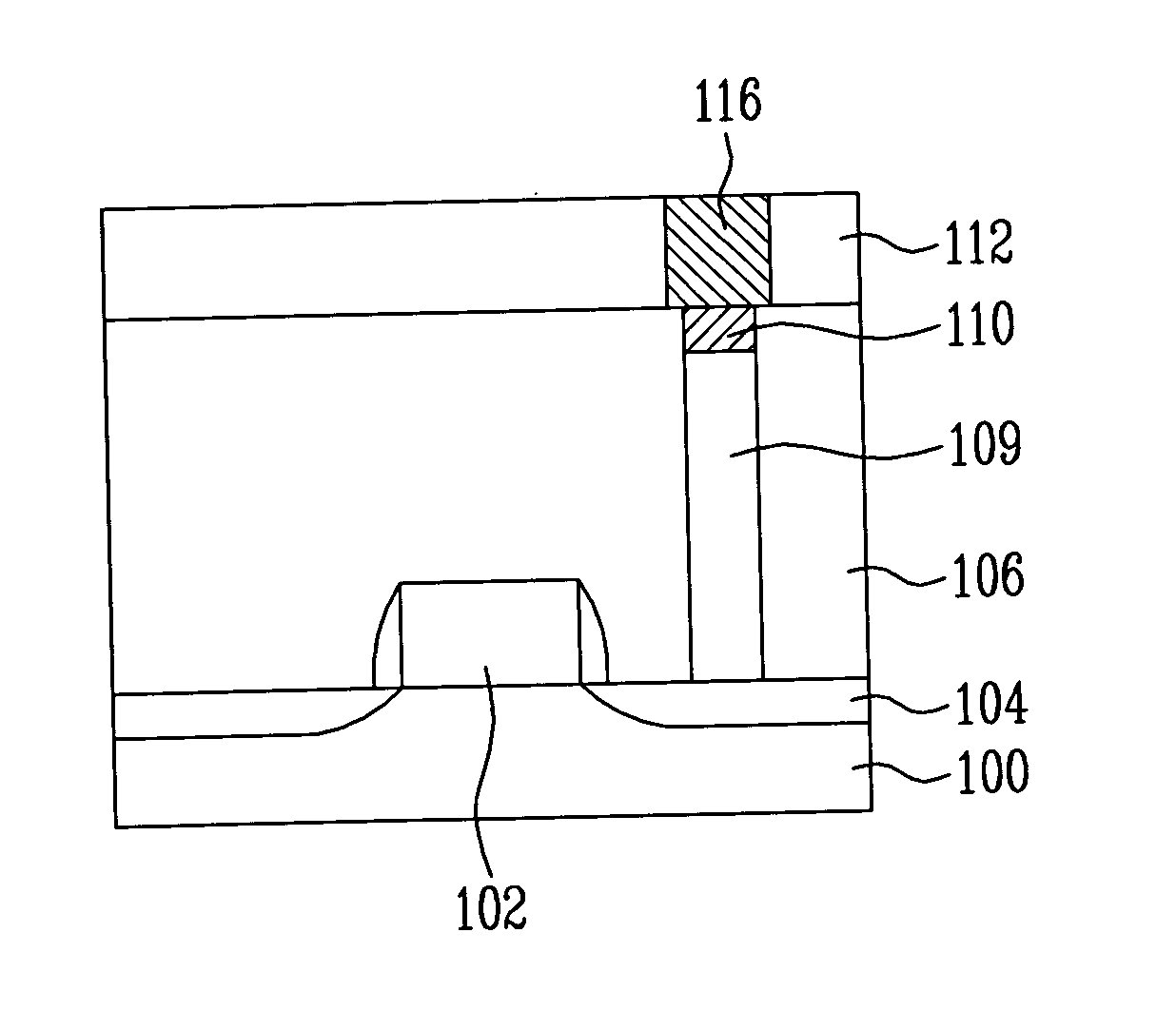
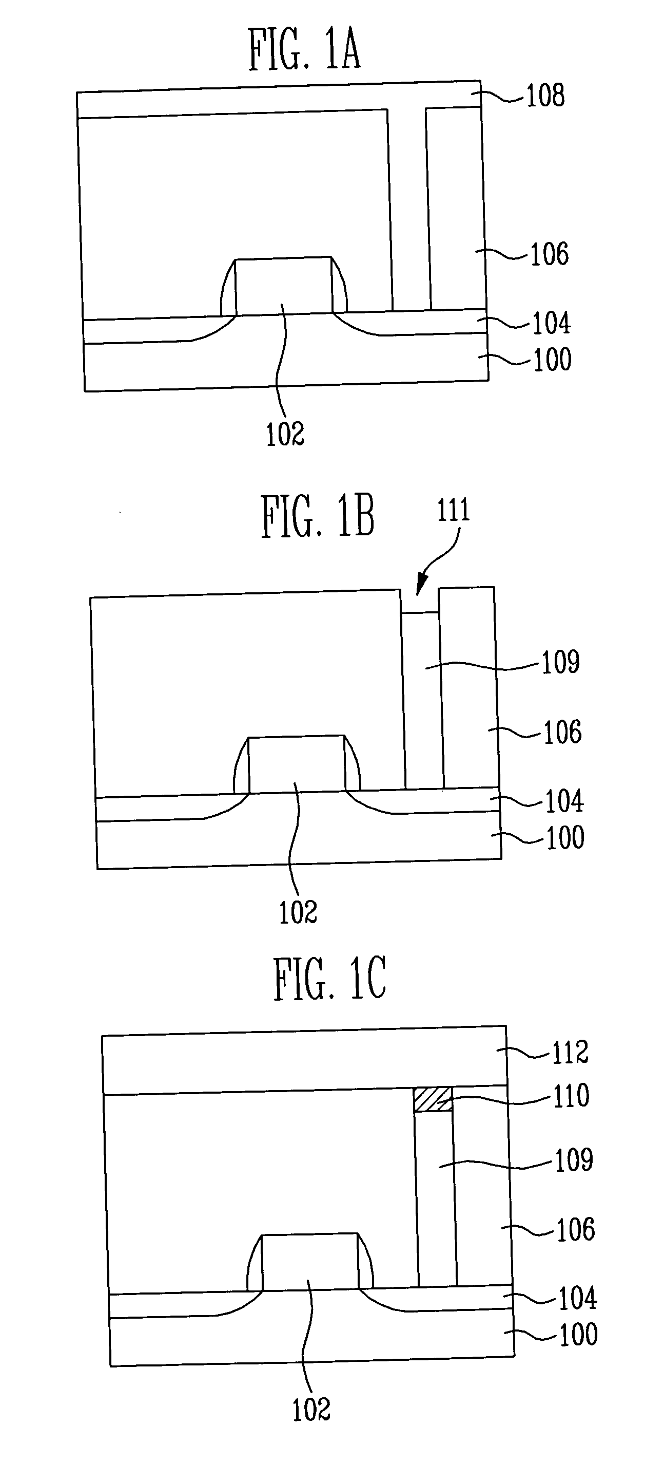
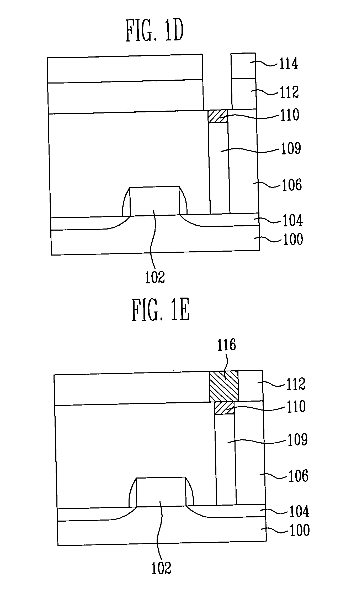
[0016] It is to be understood that the present invention is not limited to only the fabrication of NAND flash memory devices, but may be applied to not only DRAM and SRAM adopting the damascene process, but also other device fabrication technologies implementing fine conductive circuit lines. In the present invention, however, the NAND flash memory device will be described as an example.

[0017] Referring to FIG. 1A, a semiconductor substrate 100 has an isolation structure (not shown) is formed thereon. The isolation structure is formed by a Shallow Trench Isolation (STI) process to define an active region and a field region.

[0018] A gate pattern 102 having oxide film spacers formed on both sides of the gate is formed on the semiconductor substrate 100 of the active region. A junction region (a source / drain region) 104 is formed by performing a...


PUM


Abstract

A method of forming a semiconductor device includes forming a contact hole in a first interlayer insulating layer that is provided on a semiconductor substrate. The contact hole has a sidewall defined by the first interlayer insulating layer. A first conductive layer is provided within the contact hole. The first conductive layer directly contacts the first interlayer insulating layer that defines the sidewall of the contact hole. The first conductive layer is etched to define a recess within the contact hole, the recess being provided directly above the first conductive layer. An interface metal layer is provided within the recess. A second interlayer insulating layer is formed on the interface metal layer. The second interlayer insulating layer is etched to expose the interface metal layer. A second conductive layer is deposited on the exposed interface metal layer to form a bit line.

Description

BACKGROUND [0001] The present invention relates to a semiconductor device and more particularly, to a method of forming a conductive structure in a semiconductor device. [0002] As the semiconductor device shrink in size, the RC delay from capacitor coupling between adjacent conductive components are becoming a more serious concern. One such a RC delay relates to the bit line. [0003] A first interlayer insulating film is deposited on a semiconductor substrate on which various structures including the gate and the junction region had formed. A region of the first interlayer insulating film is etched to form a contact hole through which the junction region is exposed. The contact hole is filled with polysilicon to form a contact plug. [0004] A second interlayer insulating film made of boron-doped phosphorus silicate glass (BPSG), for example, is deposited on the first interlayer insulating film in which the contact plug is formed. The second interlayer insulating film is etched to form...

Claims


Application Information

Patent Timeline
Patent Type & Authority Applications(United States)
IPC IPC(8): H01L21/4763H10B69/00
CPCH01L21/76802H01L27/1052H01L21/76883H01L21/76849H10B99/00H01L21/768
Inventor AHN, JUNG RYULLEE, SEOK KIU
Owner SK HYNIX INC
Learn More