Multi-channel laser sideband frequency stabilization system
A multi-channel, laser technology, applied in the field of laser, can solve the problem of large difference between the resonant frequency of laser frequency and so on
- Summary
- Abstract
- Description
- Claims
- Application Information
AI Technical Summary
Problems solved by technology
Method used
Image


Examples
Embodiment 1
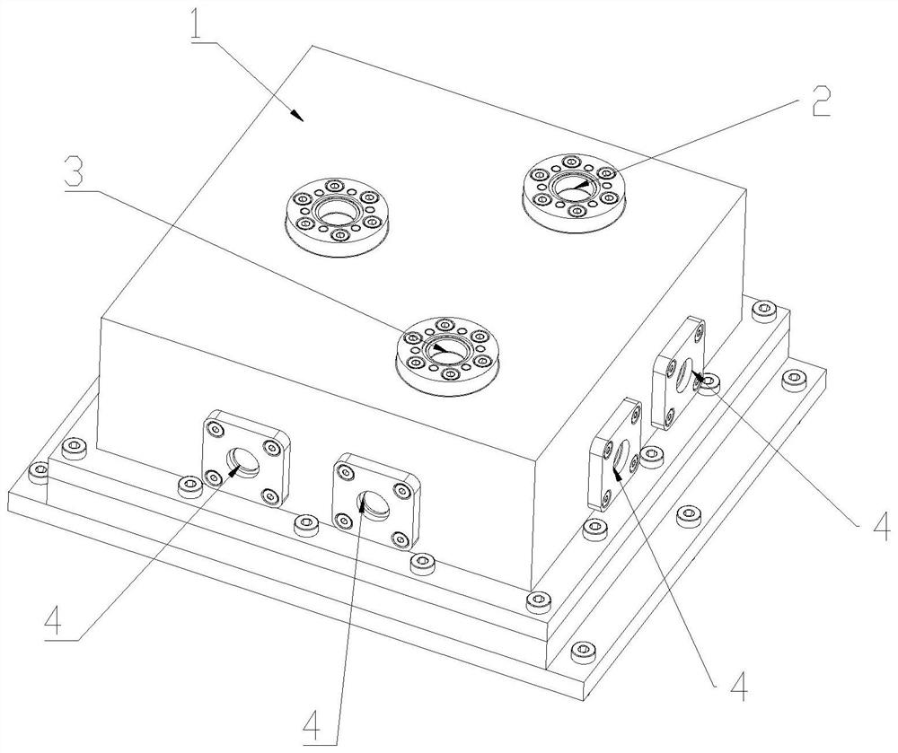
[0045] Such as Figure 1-3 As shown, the multi-channel laser sideband frequency stabilization system based on the PDH method includes a vacuum chamber 1, and also includes such as image 3 A series of optical paths in , and corresponding frequency-locked electronic devices.
[0046] The first window interface A, the second window interface B, the third window interface C, the fourth window interface D, the fifth window interface E, and the sixth window interface F are evenly distributed along the circumference of the vacuum chamber 1 , the seventh window interface G and the eighth window interface H (respectively marked as A, B, C, D, E, F, G, H, in figure 2 distributed counterclockwise along the circumference), the center points of the first window interface to the eighth window interface are located on the same distribution circle, and the top surface of the vacuum chamber 1 is provided with a first CF40 interface 2 and a second CF40 interface 3 .
[0047] The first windo...
Embodiment 2
[0058] Using the multi-channel laser sideband frequency stabilization system based on the PDH method described in Example 1, the method for locking the 854nm laser is as follows:
[0059] Step 1. The laser with a wavelength of 854nm passes through the Faraday isolator, λ / 2 wave plate HWP1, and polarization beam splitter PBS1 to select horizontally polarized light, and then passes through the beam splitter BS1, λ / 4 wave plate QWP1, λ / 2 wave plate HWP2, Lens L1, single mode polarization maintaining fiber PMF, λ / 4 wave plate QWP2, Glan Taylor prism GTP;
[0060] Step 2, the laser light passes through the fiber-coupled continuous electro-optic modulator EOM (French Ixblue company), because the difference between the required locked laser frequency f and the laser frequency ω matched by the ultrastable cavity is greater than 100MHz, in this scheme, select and The laser frequency ω=350.86565THz matched by the superstable cavity, the required locking frequency is f=350.86298THz, and ...
Embodiment 3
[0068] Using the PDH method-based multi-channel laser sideband frequency stabilization device described in Example 1, the method for locking the 397nm laser is as follows:
[0069] Step 1. The laser with a wavelength of 397nm passes through the Faraday isolator IOS, the λ / 2 wave plate HWP1, and the polarization beam splitter PBS1, and then selects horizontally polarized light, and then passes through the beam splitter BS1, the λ / 4 wave plate QWP1, and the λ / 2 wave plate in turn HWP2, lens L1, single-mode polarization-maintaining fiber PMF, λ / 4 wave plate QWP2, Glan Taylor prism GTP;
[0070] Step 2. Due to the limitation of the wavelength and the electronic driver of the EOM, the EOMs below 500nm are of the spatial type. In this solution, the spatial resonance type electro-optic modulator EOM (Qubig, Germany) is selected. The laser passes through the spatial resonant electro-optic modulator EOM, and the laser frequency ω=755.223820THz matching the ultrastable cavity is selecte...
PUM
 Abstract
Description
Claims
Application Information
 - R&D
- Intellectual Property
- Life Sciences
- Materials
- Tech Scout
- Unparalleled Data Quality
- Higher Quality Content
- 60% Fewer Hallucinations
Browse by: Latest US Patents, China's latest patents, Technical Efficacy Thesaurus, Application Domain, Technology Topic, Popular Technical Reports.
© 2025 PatSnap. All rights reserved.Legal|Privacy policy|Modern Slavery Act Transparency Statement|Sitemap|About US| Contact US: help@patsnap.com