
Patsnap Eureka
For R&D, Patsnap Eureka makes reading and utilizing patents & technical documents easy.
Patsnap Eureka AIR
Designed for self-driven R&D workflows. Generate viable solutions, solve complex R&D challenges, empower your innovation with AI.

Patsnap Eureka Materials
Designed for material experts only. Revolutionize your material R&D, from search, analyze, to developing new materials.

TechResearch
Generate reliable direction feasibility study reports for your R&D in just a few steps.

TechSeek
Discover and master advanced knowledge NOW. Basics, ideas, possibilities, all at once.

TechMind
As an expert in R&D Theories, TechMind can generates customized viable solutions instantly.

TechRisk
Analyze your overall solution with one click, know your potential R&D risks in advance.

TechMonitor
Get weekly tech updates, stay abreast of the latest tech innovations and key insights.
Thermal power plant SCR denitration reaction catalytic system
A catalytic system, thermal power plant technology, applied in chemical instruments and methods, gas treatment, membrane technology, etc., can solve problems such as inconvenient heating
- Summary
- Abstract
- Description
- Claims
- Application Information
AI Technical Summary
Problems solved by technology
Method used
Image

Examples
specific Embodiment approach 1
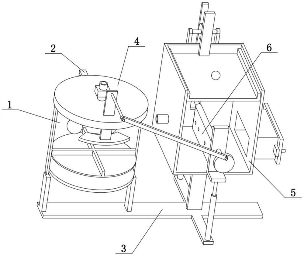
[0031] Combine below Figure 1-10 To illustrate this embodiment, the present invention relates to the field of smog denitrification, more specifically, a thermal power plant SCR denitrification catalytic system, including a cylinder 1, a circular plate 101, a disc 102, a cross edge 103, a heating wire 104 and a motor I105 , the invention is convenient to heat the mixture of solid ammonium chloride and slaked lime to generate ammonia gas for flue gas denitrification.
[0032] The upper and lower sides of the cylinder 1 are open, the lower part of the cylinder 1 is vertically slidably connected with a disc 102, the center of the lower side of the disc 102 is fixedly connected with a motor I105, and the output shaft of the upper end of the motor I105 is fixedly connected with the circular disc 105. At the center of the lower side of the plate 101 , the circular plate 101 is vertically slidably connected to the lower part of the cylinder 1 , the upper side of the circular plate 10...
specific Embodiment approach 2
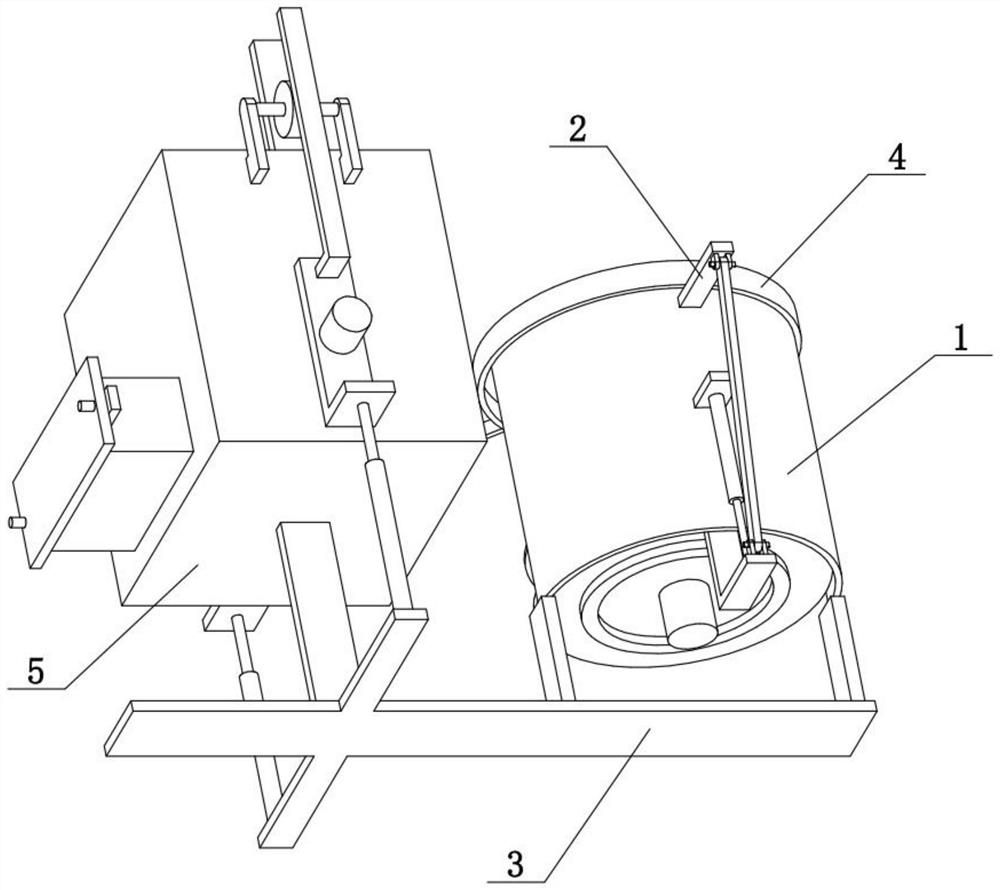
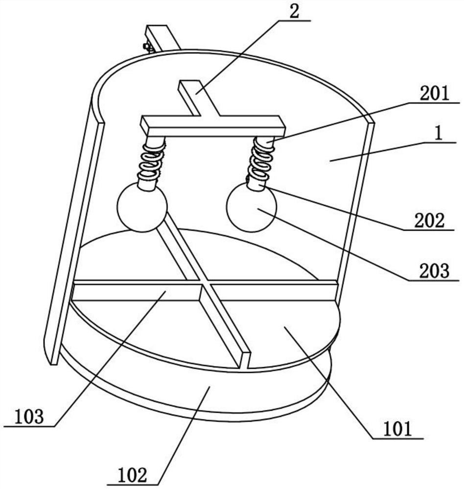
[0034] Combine below Figure 1-10To illustrate this embodiment, the SCR denitrification reaction catalytic system of the thermal power plant also includes a T-shaped frame 2, a convex cylinder I201, a convex cylinder II202 and a ball 203, and the upper part of the cylinder 1 is slidably connected with the T-shaped frame 2 in the front-rear direction. The lower side of the front part of the T-shaped frame 2 is fixedly connected with two convex cylinders I201, the lower ends of the two convex cylinders I201 are fixedly connected with springs, the upper parts of the two balls 203 are fixedly connected with convex cylinders II202, and the two convex cylinders II202 They are respectively fixedly connected to the lower parts of the two springs, and the two balls 203 are located inside the cylinder 1 . The T-shaped frame 2 can move back and forth to drive the two balls 203 to move back and forth. When the circular plate 101 moves up and down and rotates, the mixture of solid ammonium...
specific Embodiment approach 3
[0036] Combine below Figure 1-10 To illustrate this embodiment, the SCR denitration reaction catalytic system of the thermal power plant also includes a folding rod 106, an oil cylinder 1107 and an inclined connecting rod 204. Be connected with oil cylinder I107, the lower end of oil cylinder I107 is fixedly connected in the bottom of folding bar 106, the upper end of oblique connecting rod 204 is hinged on the rear portion of T-shaped frame 2, and the lower end of oblique connecting rod 204 is hinged on folding bar 106. When the oil cylinder I107 expands and contracts, it can drive the folding rod 106 to move up and down, and then drive the circular plate 101 and the disc 102 to move up and down. During the upward and downward movement of the folding rod 106, the inclined connecting rod 204 drives the T-shaped frame 2 to reciprocate back and forth, and then drives the circular plate When 101 moves up and down and rotates, the T-shaped frame 2 reciprocates back and forth, so ...
PUM
 Abstract
Description
Claims
Application Information
 - R&D Engineer
- R&D Manager
- IP Professional
- Industry Leading Data Capabilities
- Powerful AI technology
- Patent DNA Extraction
Browse by: Latest US Patents, China's latest patents, Technical Efficacy Thesaurus, Application Domain, Technology Topic, Popular Technical Reports.
© 2024 PatSnap. All rights reserved.Legal|Privacy policy|Modern Slavery Act Transparency Statement|Sitemap|About US| Contact US: help@patsnap.com