Hollow anti-resonance optical fiber

An anti-resonance, optical fiber technology, applied in cladding optical fiber, microstructure optical fiber, multi-layer core/clad optical fiber, etc., can solve the problems of narrowing transmission bandwidth, oscillating change of loss spectrum, and reducing transmission bandwidth, etc., to achieve Uniform cavity area distribution, stable loss spectrum characteristics, and effects of avoiding resonance phenomena

Active Publication Date: 2021-03-19
GUANGDONG UNIV OF TECH
View PDF6 Cites 6 Cited by
  • Summary
  • Abstract
  • Description
  • Claims
  • Application Information

AI Technical Summary

Problems solved by technology

However, if figure 1 As shown, the existing rod structure hollow anti-resonance optical fiber fixes the small capillary inside the large capillary through the glass rod, adding an additional anti-resonance layer to reduce the loss of the fiber. At the same time, the glass rod is connected to the large and small capillaries, resulting in Fano resonance. Oscillation occurs due to loss, and the transmission bandwidth is thus limited and narrowed
[0004] Another example is the optical fiber structure disclosed in the patent "a low-loss hollow-core anti-resonant optical fiber" (publication date 2020.07.31, publication number CN111474627A) filed in China, such as figure 2 As shown, it proposes the design of multi-layer hollow anti-resonant fiber for the low loss of optical fiber. The combined capillary and arc-shaped layer are fixed in the cladding region of the fiber, so that multiple anti-resonant layers can confine the o

Method used


Image

  • Hollow anti-resonance optical fiber
  • Hollow anti-resonance optical fiber
  • Hollow anti-resonance optical fiber

Examples


Embodiment 1

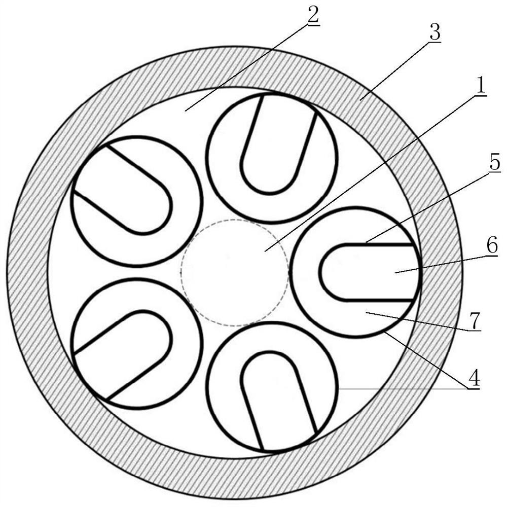
[0052] Such as Figure 4 As shown, assuming that the target transmission band is 1.2-2 μm, the target transmission window (i.e. bandwidth) is 800 nm, and the loss is reduced as much as possible, the first set of parameters can be selected as: the diameter D of the core region 1 = 40 μm, the number of capillaries 4 N=5, the gap g between any two adjacent capillaries 4=3.3μm, according to physical characteristics, the longer the wavelength, the greater the loss of the fiber, so the anti-resonance center needs to shift to the long-wavelength direction, and the anti-resonance center Wavelength λ is set as 2.1 μm, can obtain the tube wall thickness of capillary 4 and the thickness t=0.5 μm of U-shaped glass structure 5 by formula (1), can obtain the radius R=24 μm of capillary 4 by formula (2), Then the distance z=10.5 μ m between the curved end of the desirable U-shaped glass structure 5 and the capillary 4 warp direction separation, the curved end radius r=8.6 μm of the U-shaped ...

Embodiment 2

[0057] Such as Figure 4 As shown, assuming that the target transmission band is 1.5-2μm, and the target transmission window (i.e. bandwidth) is 500nm, if you want to have a good single-mode characteristic while having a wide bandwidth and low loss, you can choose the second set of parameters: core area 1 diameter D=40 μm, the number of capillary tubes 4 N=5, the gap g=3.3 μm between any two adjacent capillary tubes 4, according to physical characteristics, the longer the wavelength is, the greater the loss of the optical fiber is, so the anti-resonance center needs Offset to the long wavelength direction, the anti-resonance center wavelength λ is set to 2.1 μm, the tube wall thickness of the capillary 4 and the thickness t=0.5 μm of the U-shaped glass structure 5 can be obtained by the formula (1), and the formula (2) can Find the radius R=24 μ m of capillary 4, then the distance z=10 μ m that the curved end of desirable U-shaped glass structure 5 is separated from capillary ...


PUM

PropertyMeasurementUnit
Radiusaaaaaaaaaa

Abstract

The invention discloses a hollow anti-resonance optical fiber. A Fano resonance phenomenon can be effectively avoided by arranging a U-shaped glass structure 5 in a capillary tube 4 and enabling a contact node of the capillary tube 4 to be far away from a fiber core region 1 so that the optical fiber has a stable loss spectrum characteristic, and a relatively large transmission bandwidth is obtained; and the relatively large transmission bandwidth is ensured, the cavity of the capillary tube 4 is divided into the first type of holes 6 and the second type of holes 7 by adjusting the U-shaped glass structure 5 so that the areas of the cavities of the capillary tube 4 and the U-shaped glass structure 5 are uniformly distributed, the leakage between two glass layers (high refractive index layers) can be smaller, and an optical fiber loss is further reduced.

Description

technical field [0001] The present invention relates to the technical field of optical fiber communication, and more specifically, to a hollow-core anti-resonant optical fiber. Background technique [0002] With the rapid development of the global Internet, Internet of Things, data centers, artificial intelligence and other fields, new application scenarios continue to emerge. For example, unmanned driving, cloud computing, VR / AR, etc. have led to an exponential increase in global IP business traffic, and its information transmission is heavily dependent on the transmission rate and transmission capacity of the communication system, making people put forward higher requirements for the transmission performance of the communication network. need. However, due to the inherent defects of materials, solid optical fibers have problems such as Rayleigh scattering, material dispersion, and Kerr nonlinearity, which make it difficult to further reduce the transmission loss of existi...

Claims


Application Information

Patent Timeline
IPC IPC(8): G02B6/02G02B6/036
CPCG02B6/02295G02B6/02342G02B6/02361G02B6/036
Inventor 秦玉文郑伟钦李建平付松年许鸥
Owner GUANGDONG UNIV OF TECH
Why Eureka
Try Eureka