
High-power soliton frequency comb chip and pulse generation system and method thereof

A high-power, frequency comb technology, applied in the field of high-power soliton frequency comb chips and their pulse generation systems, can solve the problems of optical element alignment, complex coupling, ranging image refresh rate, poor ranging efficiency, and high packaging cost , to achieve the effect of meeting high power requirements, improving image refresh rate, and good security

Pending Publication Date: 2021-03-19
SUN YAT SEN UNIV
View PDF1 Cites 2 Cited by
  • Summary
  • Abstract
  • Description
  • Claims
  • Application Information

AI Technical Summary

Problems solved by technology

There are many optical components, and crystals are not easy to mass-produce. At the same time, the alignment and coupling of optical components are complicated, the packaging cost is high, and the performance stability is poor.
[0004] Patent CN103941516B, published on 2014.05.06, discloses an adjustable high-frequency pulse light source based on the carrier dispersion effect of silicon-based microring resonator, which has high output pulse stability and strong anti-interference ability; however, the ranging image The refresh rate and ranging efficiency are poor

Method used


Image

  • High-power soliton frequency comb chip and pulse generation system and method thereof
  • High-power soliton frequency comb chip and pulse generation system and method thereof
  • High-power soliton frequency comb chip and pulse generation system and method thereof

Examples


Embodiment Construction

[0034] The accompanying drawings are for illustrative purposes only, and should not be construed as limiting the present invention; in order to better illustrate this embodiment, certain components in the accompanying drawings will be omitted, enlarged or reduced, and do not represent the size of the actual product; for those skilled in the art It is understandable that some well-known structures and descriptions thereof may be omitted in the drawings. The positional relationship described in the drawings is for illustrative purposes only, and should not be construed as limiting the present invention.

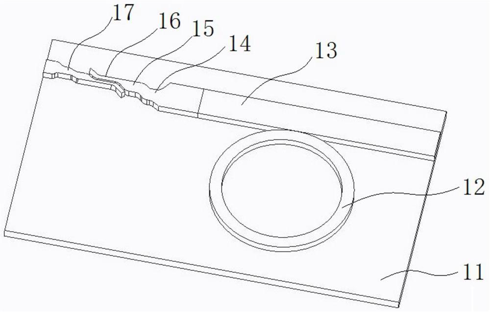
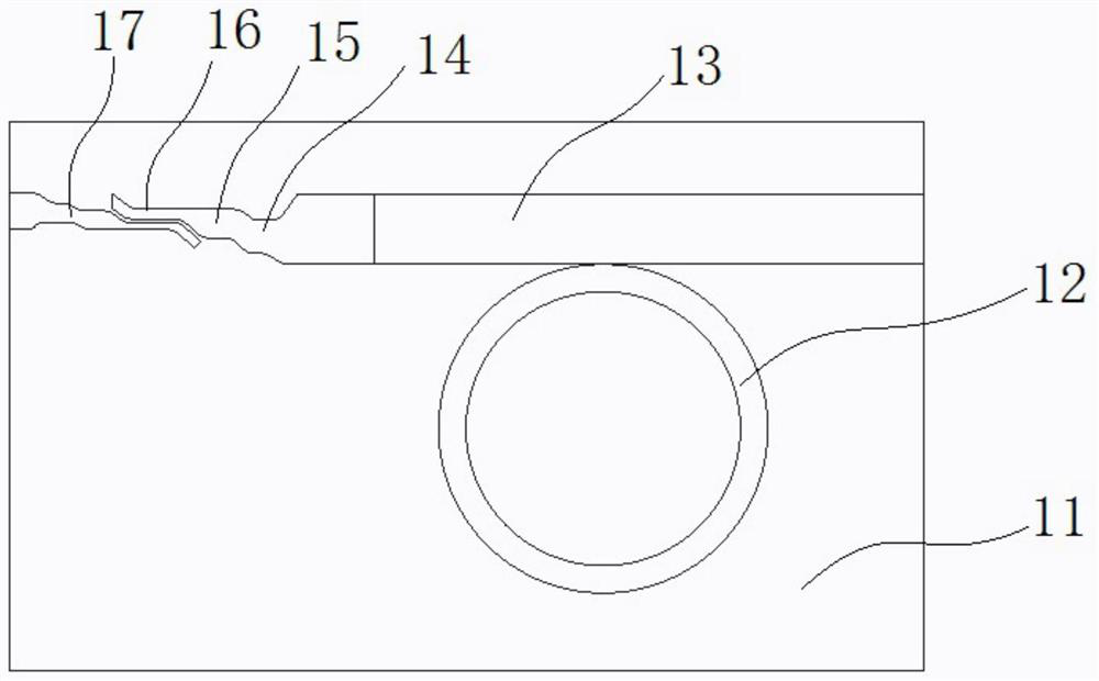
[0035] Such as figure 1 and figure 2 As shown, a high-power soliton frequency comb chip 1 includes a substrate 11, a microring resonator 12 and a straight waveguide; the microring resonator 12 and the straight waveguide are all located on the top of the substrate 11; the straight waveguide is connected from one end to the other One end sequentially includes a multimode waveg...


PUM

PropertyMeasurementUnit
Thicknessaaaaaaaaaa
Widthaaaaaaaaaa
Thickness valueaaaaaaaaaa

Abstract

The invention relates to a high-power soliton frequency comb chip and a pulse generation system and method thereof. The soliton frequency comb chip comprises a substrate, a micro-ring resonant cavityand a straight waveguide, the straight waveguide sequentially comprises a multimode waveguide, a multimode single-mode transition cone waveguide, a single-mode waveguide and a single-mode slot waveguide from one end to the other end, the wide end of the multimode single-mode transition cone is connected with the multimode waveguide, and the narrow end of the multimode single-mode transition cone is connected with one end of the single-mode waveguide. The other end of the single-mode waveguide is in coupling connection with the single-mode lot waveguide through a linear striptolot mode converter; and the micro-ring resonant cavity is positioned on one side of the multimode waveguide and is in coupling connection with the multimode waveguide. According to the invention, the thought of lasercoherent ranging is combined, the frequency comb micro-cavity structure is integrated on the micro-nano waveguide, and the generated soliton frequency comb is subjected to on-chip light amplificationto realize signal gain amplification, so that the novel integrated design of the ranging transmitting end optical system is realized, and the measurement efficiency is effectively improved.

Description

technical field [0001] The invention relates to the field of optoelectronic technology, and more specifically, to a high-power soliton frequency comb chip and its pulse generation system and method. Background technique [0002] Existing car-level lidars are divided into mechanical rotation type, MEMS type, Flash type, and phase control type according to the scanning method. At present, the mechanical rotation type and MEMS type lidar can be maturely used in the market to assist intelligent driving. The mechanical laser radar itself is the simplest to use for 360° scanning with electronically controlled turning machines. The shortcomings of optical discrete devices at the transmitting end are complicated, low in efficiency, and high in power consumption, which limit its practicability and response sensitivity in close to real and complex road conditions; while MEMS type, etc. With embedded micro-nano scanning mirrors, other non-mechanical lidars also have problems such as c...

Claims


Application Information

Patent Timeline
IPC IPC(8): G02B6/122G01S7/484G01S17/32
CPCG01S7/484G01S17/32G02B6/122G02B6/1228G02B2006/12035
Inventor 李朝晖黄向信卓少斌曹子晗宋景翠
Owner SUN YAT SEN UNIV
Learn More