Data transmission system and data transmission method based on CAN network switching

A technology of a data transmission system and a data transmission method, applied in the field of data transmission system based on CAN transfer network, can solve the problems of communication signal attenuation, inability to work, bus congestion, etc., to reduce the amount of data, reduce the load rate, and ensure real-time performance Effect

Active Publication Date: 2021-03-19
北京天乐泰力科技发展有限公司
View PDF6 Cites 0 Cited by
  • Summary
  • Abstract
  • Description
  • Claims
  • Application Information

AI Technical Summary

Problems solved by technology

[0011] 1) If the working voltage provided by the power supply system is not normal, it will make some electronic control modules not work properly for a short time, which will make the whole CAN bus system unable to work
[0012] 2) When there is a short circuit, open circuit of the communication line or a change in the physical properties of the line, the communication signal is attenuated or distorted, which will cause multiple electronic control units to be abnormal and make the CAN bus system unable to work
[0013] 3) Since the node is the electronic control module in the CAN bus system, the failure of the node is the failure of the electronic control module, which includes software failure and transmission protocol or software program defects or conflicts, so that the communication of the CAN bus system is chaotic or unable to work , this kind of failure will generally appear in batches, and the hardware failure is generally the failure of the electronic control module chip or integrated circuit, causing the CAN bus system to fail to work normally.
[0014] 4) A large number of data uploads make the CAN bus load rate higher, and the higher the load rate, the greater the probability of communication delays in low-priority nodes.
According to experiments, when the load rate is 30%, the average message transmission time of the high priority node is almost the same as the theoretical transmission time; while the low priority node has a delay of about 20%; when the load rate reaches 60% Under normal circumstances, the node with the highest priority has a delay of at least 25%, and the delay of the lowest priority has reached 4 times, which cannot meet real-time performance at all; when the average utilization rate of the bus reaches more than 70%, the communication of the bus will be Congestion may occur, and in extreme cases, error frames may occur

Method used


Image

  • Data transmission system and data transmission method based on CAN network switching
  • Data transmission system and data transmission method based on CAN network switching
  • Data transmission system and data transmission method based on CAN network switching

Examples


Embodiment 2

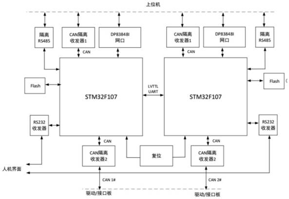
[0062] Such as image 3 As shown, compared with the embodiment, this embodiment adds a reset module, which is used to reset when the data transmission system fails.

[0063] Such as Figure 4 As shown, this embodiment adopts 8 CAN node sub-modules to form a small CAN ring network, the amount of data transmitted on the CAN bus is greatly reduced, and the load rate of the CAN bus is reduced accordingly. The lower the load rate of the CAN bus, the more guaranteed Real-time, but if the load rate is too low, enough data cannot be transmitted. This is a problem with CAN, and real-time performance cannot be guaranteed when the amount of data is large. The general saying is that the load rate of about 30% is the best.

[0064] Calculate the load rate by the formula:

[0065]

[0066] Combined with the characteristics of the subway platform doors, about 2 groups are formed into a small CAN ring network, that is, the number of CAN nodes in the CAN ring network of the A-type car is...


PUM


Abstract

The invention discloses a data transmission system based on CAN network switching. The data transmission system comprises a CAN looped network module for collecting real-time state data of each platform door and transmitting the real-time state data to a CAN network switching module, the CAN network switching module for receiving the real-time state data, converting the real-time state data into data information suitable for an Ethernet transmission module and transmitting the data information to the Ethernet transmission module, the Ethernet transmission module used for transmitting data information to the PSC, the PSC and PSA used for processing the data information, and a display system used for displaying the information. The CAN looped network module is composed of a plurality of CANlooped networks, each CAN looped network comprises a plurality of CAN nodes, each CAN node comprises a DCU, and the DCUs are in one-to-one correspondence with the sliding doors and used for collectingreal-time state data. According to the data transmission system based on CAN network switching provided by the invention, double CAN looped networks are used internally, and double network cables areused externally for communication, so that data and communication sharing is realized, and the reliability of the system is improved.

Description

technical field [0001] The invention relates to the field of rail transit data transmission, in particular to a CAN-based data transmission system and a data transmission method. Background technique [0002] The subway platform door is an important part of the urban rail transit field. There are two types of subway vehicles, type A and type B. Among them, there are 5 sets of doors in each compartment of the A-type car, and 4 sets of doors in each compartment of the B-type car. There are 4 groups, 6 groups, 8 groups and so on in the number of groups. The number of sliding doors in the platform door is consistent with the number of subway train compartment doors. Each sliding door corresponds to a set of platform door controller (DCU). Each set of DCU needs to collect various state information of the door body and upload it to The central control system (PSC) of the platform door, such as a platform door on one side of a 6-group B-type car, must have 24 sets of DCUs to upl...

Claims


Application Information

Patent Timeline
Patent Type & Authority Applications(China)
IPC IPC(8): H04L12/40
CPCH04L12/40013H04L12/40189H04L2012/40215Y02P90/02
Inventor 刘春梅
Owner 北京天乐泰力科技发展有限公司
Why Eureka
Try Eureka