Self-biased differential drive rectifier circuit with wide dynamic range

A technology of rectifier circuit and wide dynamic range, which is applied in the direction of output power conversion device, electrical components, AC power input conversion to DC power output, etc. It can solve the problems of reducing the efficiency of differential drive rectifiers and reducing the conduction voltage drop, etc., to achieve Widening the dynamic range and reducing the effect of reverse current

Active Publication Date: 2021-03-23
SOUTHEAST UNIV
View PDF14 Cites 2 Cited by
  • Summary
  • Abstract
  • Description
  • Claims
  • Application Information

AI Technical Summary

Problems solved by technology

The differential drive rectifier uses MOS tube switches to realize AC-DC conversion, which greatly reduces the conduction voltage drop and optimizes the sensitivity parameters; however, due to the bidirectional conduction characteristics of the MOS tube switches, under high input power, some of the collected charges will be The reverse flow back to the RF input through the MOS tube switch reduces the efficiency of the differential drive rectifier

Method used


Image

  • Self-biased differential drive rectifier circuit with wide dynamic range
  • Self-biased differential drive rectifier circuit with wide dynamic range
  • Self-biased differential drive rectifier circuit with wide dynamic range

Examples


Embodiment Construction

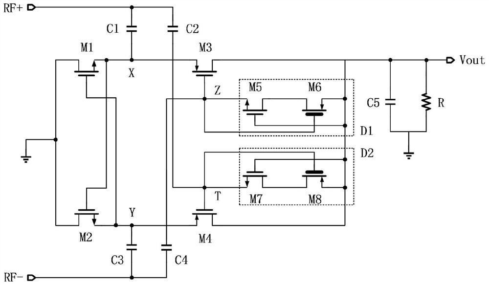
[0021] The circuit is composed of a conventional differential drive rectifier and two first diodes D1 and D2 with special structures.

[0022] The input signal is RF+ and RF-, the output signal is V out .

[0023] A conventional differential drive rectifier is composed of a first NMOS transistor M1, a second NMOS transistor M2, a first PMOS transistor M3, and a second PMOS transistor M4, and the first diode D1 is composed of a third NMOS transistor M5 and a third PMOS transistor M6. , the second diode D2 is composed of the fourth NMOS transistor M7 and the fourth PMOS transistor M8; wherein the first NMOS transistor M1, the second NMOS transistor M2, the third NMOS transistor M5, and the fourth NMOS transistor M7 are medium-threshold NMOS transistors The first PMOS transistor M3 and the second PMOS transistor M4 are medium-threshold PMOS transistors, and the third PMOS transistor M6 and fourth PMOS transistor M8 are high-threshold PMOS transistors. Connect the input signal R...


PUM


Abstract

The invention discloses a self-biased differential drive rectifier circuit with a wide dynamic range. The differential drive rectifier circuit is composed of a differential drive rectifier composed ofa first NMOS transistor (M1), a second NMOS transistor (M2), a first PMOS transistor (M3) and a second PMOS transistor (M4), and a diode of a special structure composed of a first diode (D1) and a second diode (D2). Input signals are RF+ and RF- and are connected with the input end of the differential drive rectifier through the first capacitor (C1) and the second capacitor (C2), the output end of the differential drive rectifier is connected with the first diode (D1) and the second diode (D2) which are connected in parallel, and the output ends of the first diode (D1) and the second diode (D2) are output signals Vout. Feedback is introduced from an output port through a diode, so that bias is provided for a grid electrode of an output PMOS of the differential drive rectifier, and the grid voltage of the differential drive rectifier is controlled. Under the condition of high input power, the reverse current of the differential drive rectifier is effectively reduced, and the dynamic range of high-efficiency output of the differential drive rectifier circuit is widened.

Description

technical field [0001] The invention belongs to the field of rectifier circuits, in particular to a self-bias differential drive rectifier circuit capable of realizing a wide dynamic range. Background technique [0002] Wireless power transmission technology is widely used in radio frequency identification, implanted biomedical equipment, wireless sensors and other fields. Its core module is an RF-DC power conversion circuit, which can convert the RF energy collected from the antenna end into a stable DC Power, providing a stable voltage for subsequent circuit modules. [0003] In the field of RF energy harvesting, there are mainly two rectifier structures: Dickson type and cross-coupled differential drive type. The Dickson type rectifier realizes the conversion of AC and DC through a diode, but the conduction voltage drop of the diode limits the conversion efficiency of the rectifier at low input power. In a low radio frequency energy environment, in order to ensure high ...

Claims


Application Information

Patent Timeline
Patent Type & Authority Applications(China)
IPC IPC(8): H02M7/219H02M1/088H04B5/00
CPCH02M1/088H02M7/219H04B5/0037
Inventor 吴建辉瞿剑谢祖帅吴志强周全才李红
Owner SOUTHEAST UNIV
Why Eureka
Try Eureka