Linearized bias circuit and radio frequency power amplifier

A power amplifier and bias circuit technology, applied in power amplifiers, amplifiers, and improving amplifiers to reduce temperature/power supply voltage changes, etc. problems, to achieve the effect of solving poor linearity, stabilizing the static operating point, and maintaining stability

Pending Publication Date: 2021-03-23
GUANGDONG UNIV OF TECH +1
View PDF1 Cites 2 Cited by
  • Summary
  • Abstract
  • Description
  • Claims
  • Application Information

AI Technical Summary

Problems solved by technology

[0004] The present invention provides a linearized bias circuit and a radio frequency power amplifier in order to overcome the technical defect that the area of ​​the final triode and the capacitor is too large when solving the problem of the poor linearity of the high power output of the power amplifier in the prior art

Method used


Image

  • Linearized bias circuit and radio frequency power amplifier
  • Linearized bias circuit and radio frequency power amplifier
  • Linearized bias circuit and radio frequency power amplifier

Examples


Embodiment 1

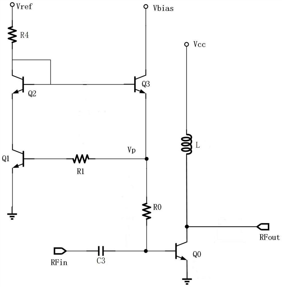
[0043] In this embodiment, a power amplifier using a linearization bias is provided, and the power amplifier using a linearization bias is such as figure 2 As shown, including the RF amplifier unit circuit and the linearization bias circuit,

[0044] Wherein, the linearization bias circuit includes: a first transistor Q1, a second transistor Q2, a third transistor Q3, a first resistor R1, a base ballast resistor R0, and a fourth resistor R4; The base of the first transistor Q1 is electrically connected to one end of the first resistor R1, the collector of the first transistor Q1 is electrically connected to the emitter of the second transistor Q2, and the first The emitter of the triode Q1 is grounded, the base of the second triode Q2 is electrically connected to the collector, the collector of the second triode Q2 is electrically connected to one end of the fourth resistor R4, and the fourth resistor R4 The voltage at the other end of the transistor Q2 is a reference voltag...

Embodiment 2

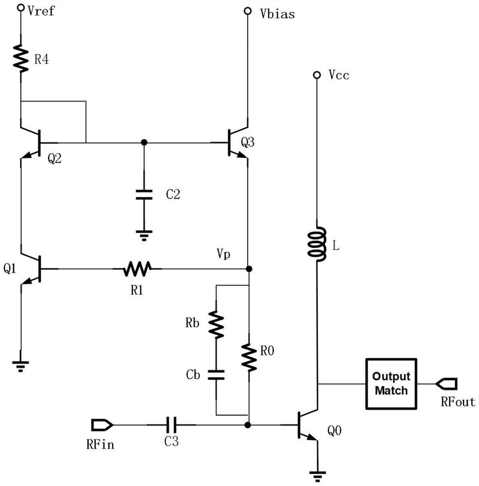
[0052] like figure 2 As shown, on the basis of Embodiment 1, a second capacitor C2, an RC circuit, and an output matching circuit (OutputMatch) are added in this embodiment. One end of the second capacitor C2 is grounded, and the other end is connected to the third triode The base of Q3 is electrically connected, the RC circuit includes: RC resistor Rb, RC capacitor Cb, RC resistor Rb and RC capacitor Cb are connected in series and connected in parallel at both ends of the base ballast resistor R0, and the output matching circuit is connected in series with the bias transistor Between the collector of Q0 and the signal output terminal.

[0053] The series circuit of RC resistor Rb and RC capacitor Cb is connected in parallel on the base ballast resistor R0, which reduces the impedance of RF coupling into the bias circuit. As the input power increases, the RF signal coupled into C2 and Q3 will also increase. increase, leading to a decrease in Vbe3, due to the existence of C2,...


PUM


Abstract

The invention discloses a linearized bias circuit and a radio frequency power amplifier, and belongs to the technical field of radio frequency power amplifiers. The radio frequency power amplifier comprises a linearized bias circuit and a radio frequency amplifier unit circuit. The linearized bias circuit is electrically connected with the radio frequency amplifier unit circuit; by improving the circuit structure and introducing the structure of the current mirror, temperature compensation is carried out for the problem of heating under high power, the temperature drift of a static working point is inhibited, and the problem of poor high-power output linearity of the power amplifier is solved while the area of the bias circuit is not excessively increased.

Description

technical field [0001] The present invention relates to the technical field of radio frequency power amplifiers, more specifically, to a linearization bias circuit and a radio frequency power amplifier. Background technique [0002] With the development of wireless communication technology, people have put forward higher requirements for the speed and stability of wireless transmission. In this context, 5G technology has become one of the hottest topics in the field of wireless communication. Compared with the previous 4G and 3G, the biggest difference of 5G technology is the improvement of the modulation method. 5G adopts a modulation method with higher spectrum efficiency to increase the information transmission rate. The modulation method with higher spectral efficiency brings high peak-to-average ratio (PAR) of the signal. For the RF front-end, high PAR will bring serious nonlinear distortion, especially for power amplifiers, high PAR signals The peak value of the power...

Claims


Application Information

Patent Timeline
Patent Type & Authority Applications(China)
IPC IPC(8): H03F1/30H03F3/20
CPCH03F1/302H03F3/20
Inventor 刘子林章国豪
Owner GUANGDONG UNIV OF TECH
Why Eureka
Try Eureka