
Steel with bionic multi-level structure and machining process thereof

A processing technology, multi-level technology, applied in the direction of metal material coating technology, coating, manufacturing tools, etc., can solve the problems that the material strength and toughness cannot be achieved at the same time, and the nucleation resistance and long crack growth resistance cannot be achieved at the same time. Great maneuverability and variety of effects

Active Publication Date: 2021-03-26
SHIHEZI UNIVERSITY +1
View PDF4 Cites 0 Cited by
  • Summary
  • Abstract
  • Description
  • Claims
  • Application Information

AI Technical Summary

Problems solved by technology

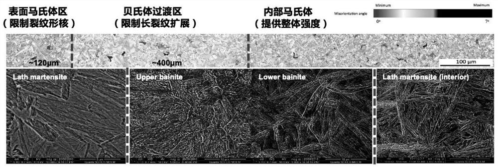
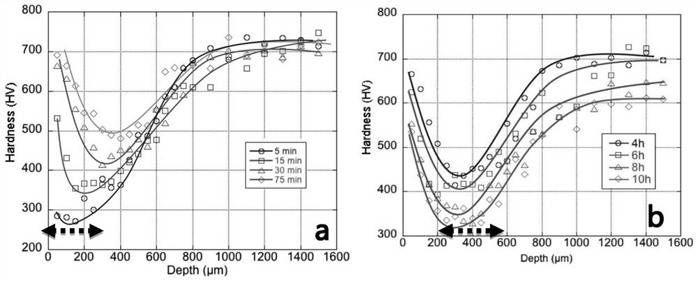
[0005] The object of the present invention is to provide a processing technology for steel with a bionic multi-level structure, through the decarburization and carburizing process, the diffusion of carbon element is controlled at the austenite temperature, so that the carbon element has a designed distribution in the sample, Then affect the distribution of microstructure phase transformation and mechanical properties during the cooling process of the sample, forming a bionic steel with a hierarchical structure at the macro scale, making the mechanical properties diverse in the overall space to meet the different stages of fatigue crack growth on the material properties. demand, to bypass the classic problem in fatigue design—material strength and toughness can’t be achieved at the same time, that is, to use hierarchical structure design to solve the traditional fatigue design of “homogeneous high-strength steel fatigue crack nucleation resistance and long crack growth resistance cannot be The important question of having both

Method used


Image

  • Steel with bionic multi-level structure and machining process thereof
  • Steel with bionic multi-level structure and machining process thereof
  • Steel with bionic multi-level structure and machining process thereof

Examples


Embodiment 1

[0065] The specific operation steps are as follows:

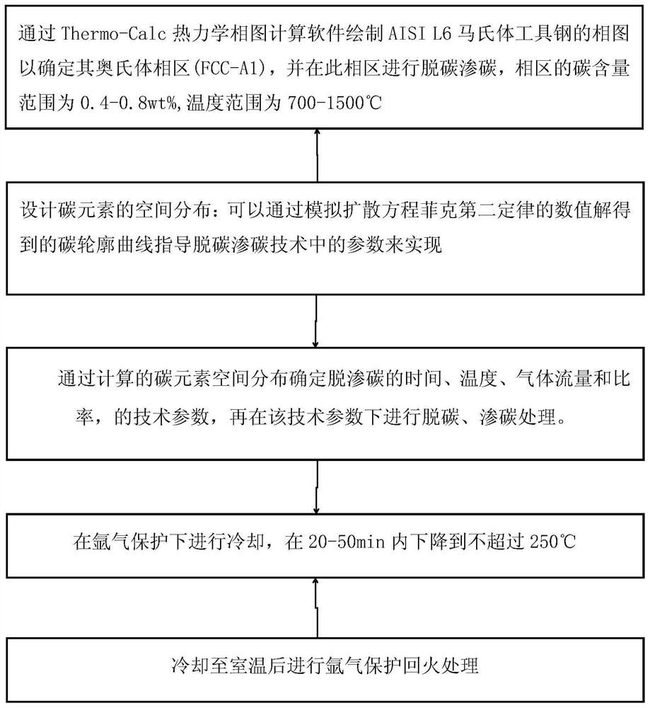
[0066] S10: Taking AISI L6 martensitic tool steel (0.56wt%C, 1.1wt%Cr, 1.7wt%Ni0.5wt%Mo, 0.1wt%V) with a thickness of 3mm as the research object, it was changed by decarburization and carburizing technology The spatial distribution of carbon in the steel is used to control the phase transition interval, and then the microstructure of the martensitic steel is multi-layered, and finally controls the distribution of its spatial mechanical properties to meet the needs of fatigue design. This was inspired by the successful application of the multilayered structure of the human tooth under fatigue loading. Divided into the following three steps:

[0067] (1) Draw the phase diagram of AISI L6 martensitic tool steel by Thermo-Calc thermodynamic phase diagram calculation software to determine its austenite phase region (FCC_A1), and carry out decarburization and carburization in this phase region, the carbon in the phase region Th...

Embodiment 2

[0078] A bearing factory conducts tests with standard fatigue components. The samples used are ordinary homogeneous steel, and the width of the fatigue test site is 3mm. Its tensile strength is 1500Mpa, fatigue strength is 700Mpa, less than 50% of tensile strength.

[0079] For small-sized samples, the fatigue cycle is dominated by surface crack nucleation, so compared with homogeneous martensite, the hierarchical surface high-strength martensite layer can effectively delay fatigue crack nucleation.

[0080] Adopting the technical solution of the present invention to carry out the multi-level structure to improve the anti-fatigue performance includes the following steps:

[0081] (1) Carry out composition detection to iron and steel, confirm that carbon content is 0.5wt%, then place component in tube furnace with 500cm 3 / min into the argon to remove the air, and then heated to 930 ℃ for 10min, through 430cm 3 / min of wet hydrogen decarburization for 20h;

[0082] (2) Befor...

Embodiment 3

[0087] A bearing factory conducts tests with standard fatigue components. The samples used are ordinary homogeneous steel materials, and the width of the fatigue test site is 10mm. Its tensile strength is 1000Mpa, fatigue strength is 400Mpa, less than 50% of tensile strength.

[0088] For intermediate-sized samples, the most effective strategy is to imitate the multilayer structure of teeth, forming high-strength martensite on the surface to limit crack nucleation, forming lower bainite in the middle to delay long crack growth, while maintaining martensite in the core region. body to support the bulk strength of the material,

[0089] Adopting the method of the present invention to carry out the multi-level structure to improve the anti-fatigue performance comprises the following steps:

[0090] (1) Carry out composition detection to iron and steel, confirm that carbon content is 0.6wt%C, then place component in tube furnace with 500cm 3 / min into the argon, and then heated ...


PUM

PropertyMeasurementUnit
thicknessaaaaaaaaaa
tensile strengthaaaaaaaaaa
fatigue strengthaaaaaaaaaa

Abstract

The invention relates to a steel with a bionic multi-level structure and a machining process thereof. The machining process of the steel with the bionic multi-level structure comprises the following steps: S10, conducting decarburization and carburization in the range of an austenite phase area of a steel raw material, wherein the carbon content of the austenite phase region is 0.4-0.8wt%, and thetemperature of the austenite phase region is 700-1500 DEG C; S20, cooling, specifically, cooling the steel raw material treated in the step S20 under the protection of argon, wherein the temperatureis decreased to 250 DEG C or below within 20-50 minutes; and S30, after the steel raw material treated in the step S20 is cooled to room temperature, conducting tempering treatment in the argon atmosphere to obtain the steel with the bionic multi-layer structure. According to the machining process, a decarburization and carburization technology is adopted to change the spatial distribution of carbon elements in the steel to control a phase change interval, so that the microstructure of martensitic steel is hierarchical, and finally the spatial mechanical property distribution of the martensitic steel is controlled to meet the fatigue design requirement.

Description

technical field [0001] The invention belongs to the technical field of metal materials, and in particular relates to a steel material with a bionic multi-level structure and a processing technology thereof. Background technique [0002] At the end of 2018, the national railway operating mileage reached 131,000 kilometers, and the compound growth rate of newly added railway mileage from 2013 to 2018 was 8%. Steel is used as the main structural material of railway engineering because of its advantages in price, mechanical properties and recyclability. High-performance steel rails have broad application prospects, but the application of many high-strength steels in mobile structures is limited by their fatigue properties. This form of loading occurs in almost all engineering applications, and approximately 90% of metallic material failures are due to fatigue failure. Therefore, a new fatigue design method and idea to improve the fatigue life of mobile structures is of great e...

Claims


Application Information

Patent Timeline
Patent Type & Authority Applications(China)
IPC IPC(8): C21D3/04C21D1/74C23C8/22C21D11/00
CPCC21D3/04C21D1/74C23C8/22C21D11/00
Inventor 杨盛超张新宇刘志勇刘伟黄超吴建宁孟桂花李文娟曲欣崔林
Owner SHIHEZI UNIVERSITY
Learn More