Eureka AIR delivers breakthrough ideas for toughest innovation challenges, trusted by R&D personnel around the world.

Magneto-rheological damper with double annular damping gaps

A magnetorheological damper, double ring technology, applied in the direction of shock absorber, shock absorber, spring/shock absorber, etc., can solve the problem of low utilization rate of magnetic field, leakage of magnetorheological fluid, and increase of controllable damping force Limited range and other problems, to achieve the effect of improving the range of controllable damping force and dynamic range, the convenience of lead-out problems, and avoiding the problem of easy leakage

Active Publication Date: 2021-03-26
XI AN JIAOTONG UNIV
View PDF5 Cites 2 Cited by
  • Summary
  • Abstract
  • Description
  • Claims
  • Application Information

AI Technical Summary

Problems solved by technology

Because the piston head occupies a large space, the effective damping gap is only located at both ends of the piston head, resulting in a very low utilization of the magnetic field; (2) The dynamic range is small
The superiority of magnetorheological damper performance is generally reflected in the dynamic range, while the viscous damping force and controllable damping force of the two common magnetorheological dampers are both low, and the range of controllable damping force increase is limited, causing The dynamic range is small; (3) When the damping gap is located on the piston head, it is easy to cause magnetic flux leakage, which makes it difficult to achieve the expected magnetic field effect; (4) The lead-out line of the piston head coil is inconvenient, and sometimes it is easy to have magnetorheological changes liquid leakage problem

Method used


Image

  • Magneto-rheological damper with double annular damping gaps
  • Magneto-rheological damper with double annular damping gaps
  • Magneto-rheological damper with double annular damping gaps

Examples


Embodiment Construction

[0036] In describing the present invention, it should be understood that the terms "center", "longitudinal", "transverse", "upper", "lower", "front", "rear", "left", "right", " The orientation or positional relationship indicated by "vertical", "horizontal", "top", "bottom", "inner", "outer", "side", "end", "side" etc. is based on the Orientation or positional relationship is only for the convenience of describing the present invention and simplifying the description, and does not indicate or imply that the referred device or element must have a specific orientation, be constructed and operated in a specific orientation, and thus should not be construed as a limitation of the present invention. In addition, the terms "first" and "second" are used for descriptive purposes only, and cannot be interpreted as indicating or implying relative importance or implicitly specifying the quantity of indicated technical features. Thus, a feature defined as "first" and "second" may explicit...


PUM


Abstract

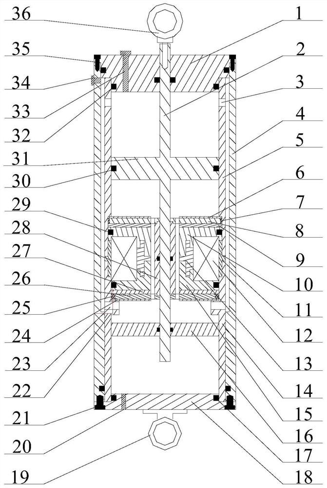
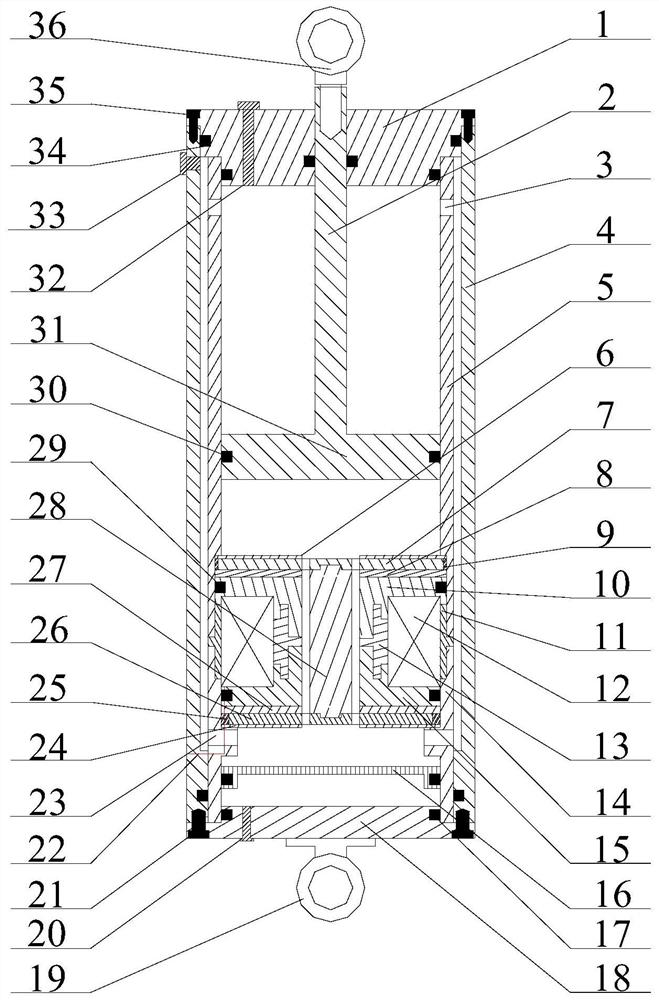
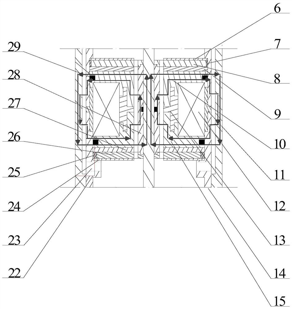
The invention discloses a magneto-rheological damper with double annular damping gaps. The damper is characterized in that an inner cylinder barrel is arranged inside an outer cylinder barrel, and theinner cylinder barrel sequentially comprises an inner cylinder barrel upper section, an inner cylinder barrel middle section and an inner cylinder barrel lower section from top to bottom; the outer cylinder barrel, the inner cylinder barrel upper section and the inner cylinder barrel lower section are made of high-magnetic-conductive materials, and the inner cylinder barrel middle section is madeof a non-magnetic-conductive material; cylinder barrel upper covers are arranged at the upper ends of the outer cylinder barrel and the inner cylinder barrel, cylinder barrel lower covers are arranged at the lower ends, a piston rod is arranged inside the inner cylinder barrel, one end of the piston rod extends out of the cylinder barrel upper cover, and the other end of the piston rod penetratesthrough a low-carbon steel disc; a piston head is arranged on the piston rod, a damping generator is arranged between the piston head and the low-carbon steel disc, and the upper end and the lower end of the damping generator are each provided with a non-magnetic-conductive material used for isolating a magnetic field; and a high-magnetic-conductivity material and a non-magnetic-conductivity material for changing magnetic field distribution are arranged in the middle of the damping generator. According to the damper, the magnetic field utilization rate is improved, and the damping force rangeand the dynamic range are remarkably improved.

Description

technical field [0001] The invention belongs to the technical field of magnetorheological dampers, in particular to a magnetorheological damper with double annular damping gaps. Background technique [0002] Magnetorheological fluid is a kind of controllable fluid, which is a relatively active research in smart materials. In the absence of a magnetic field, the magnetorheological fluid exhibits low-viscosity non-Newtonian fluid characteristics; while under the action of a magnetic field, it exhibits high-viscosity, low-fluidity Bingham characteristics. The magnetorheological damper based on magnetorheological fluid is a semi-active damping device, which is widely used in construction, artillery, automobiles, aerospace and other fields. [0003] Magneto-rheological dampers come in a variety of designs, but the most common is to place the coil on the piston head. The principle of the magnetorheological damper is that the direction of the magnetic field at the effective damp...

Claims


Application Information

Patent Timeline
Patent Type & Authority Applications(China)
IPC IPC(8): F16F9/53F16F9/32F16F9/34F16F9/36F16F9/43
CPCF16F9/3207F16F9/3257F16F9/34F16F9/368F16F9/43F16F9/535
Inventor 董龙雷严健周嘉明官威欧阳钦山
Owner XI AN JIAOTONG UNIV
Why Eureka
Eureka Blog
Learn More