Liquid fuel burning micro-combustor applied to micro-thermal photoelectric system

A technology of liquid fuel and micro-combustor, which is applied to the combustion of liquid fuel and gaseous fuel, the combustion of catalytic material, and the combustion method. It can solve the problems of single gas fuel, insufficient combustion, and instability, and achieve complete Combustion, improved combustion efficiency, less pollution effect

Pending Publication Date: 2021-03-26
JIANGSU UNIV
View PDF8 Cites 2 Cited by
  • Summary
  • Abstract
  • Description
  • Claims
  • Application Information

AI Technical Summary

Problems solved by technology

However, in conventional flat-plate burners, the gas fuel used is relatively single, and when the heat generated by gas combustion is less than the heat lost by the tube wall, quenching occurs
At the same time, due to the short residence time of the gas in the burner, the combustion will be insufficient and unstable.

Method used


Image

  • Liquid fuel burning micro-combustor applied to micro-thermal photoelectric system

Examples


Embodiment Construction

[0022] The present invention will be further described below in conjunction with the accompanying drawings and specific embodiments, but the protection scope of the present invention is not limited thereto.

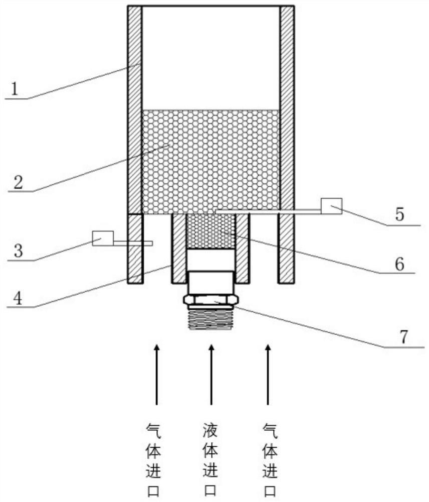
[0023] Such as figure 1 As shown, the micro-combustor of the present invention, which is applied to the micro-thermal photoelectric system for burning liquid fuel, includes a feed channel and a combustion chamber 1, and the feed channel is located at the entrance of the combustion chamber 1, and the feed channel It includes a gaseous fuel channel 4 and a liquid fuel channel, the gaseous fuel channel 4 surrounds the liquid fuel channel, the middle part of the gaseous fuel channel 4 is provided with a first igniter 3, and the junction of the liquid fuel channel and the combustion chamber 1 is provided with The second igniter 5 first ignites the gaseous fuel channel through the first igniter 3, and is used for preheating the liquid fuel channel. The first igniter 3 is an el...


PUM


Abstract

The invention provides a liquid fuel burning micro-combustor applied to a micro-thermal photoelectric system. The micro-combustor comprises feeding channels and a combustion chamber, wherein the feeding channels are positioned at inlets of the combustion chamber and comprise a gas fuel channel and a liquid fuel channel, the gas fuel channel surrounds the liquid fuel channel, a first igniter is arranged in the middle of the gas fuel channel, a second igniter is arranged at the junction of the liquid fuel channel and the combustion chamber, and the gas fuel channel is ignited through the first igniter for preheating the liquid fuel channel. By using the gas and liquid dual fuel inlets, two fuels are effectively and fully premixed, so that the combustion is more stable, by using the gas and liquid dual fuels, the energy conversion efficiency is improved, so that the combustion is more sufficient, and meanwhile, the emission of pollutants such as NOX in the combustion product is reduced.

Description

technical field [0001] The invention relates to the technical field of micro-scale thermal photoelectric energy conversion, in particular to a micro burner for burning liquid fuel applied to a micro thermal photoelectric system. Background technique [0002] Under the strong impetus of micromachining technology, continuous breakthroughs have been made in the research and development of micromechanical and electromechanical products, but the power supply part has not made great progress, resulting in the complete microelectromechanical system (MEMS) being too large, too heavy or Cannot work for a long time, which has become the bottleneck of MEMS development. However, the proposal of a combustion-based micro-power device is expected to solve this problem well, so it has attracted the attention of many scholars. [0003] As a typical micro-power device, the micro-thermal photoelectric system uses the heat energy generated by the combustion of hydrocarbon fuel in the micro-com...

Claims


Application Information

Patent Timeline
Patent Type & Authority Applications(China)
IPC IPC(8): F23C13/00F23C13/08F23C1/08
CPCF23C13/00F23C13/08F23C1/08
Inventor 苟杰周海峰卢青波
Owner JIANGSU UNIV
Why Eureka
Try Eureka