
Negative pressure drying device

A drying device and negative pressure technology, applied in the directions of drying, drying machine, drying gas arrangement, etc., can solve problems such as reducing the quality of silicon wafer finished products, and achieve the effect of good dehydration effect and good drying effect.

Pending Publication Date: 2021-03-26
苏州宝馨智能制造有限公司
View PDF10 Cites 2 Cited by
  • Summary
  • Abstract
  • Description
  • Claims
  • Application Information

AI Technical Summary

Problems solved by technology

[0003] Existing silicon wafers for solar cells are usually processed by wet methods, in which the traditional drying tank for drying silicon wafers uses a single hot air drying mode, and the slugs carrying silicon wafers outside are prone to generate high-humidity air and cause Circulating drying inside the tank makes it easier to form water stains and oxide films on the surface of the silicon wafer, reducing the quality of the finished silicon wafer; and the structure of the existing drying tank cannot match the previous tank position to achieve slow pulling at a lower temperature to clean

Method used


Image

  • Negative pressure drying device
  • Negative pressure drying device

Examples


Embodiment

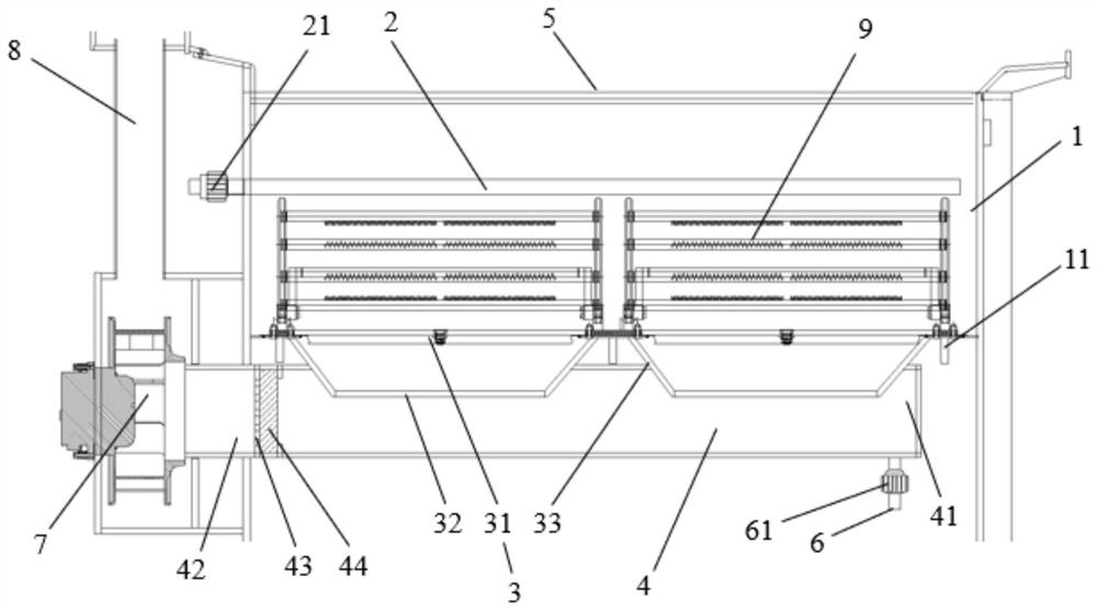
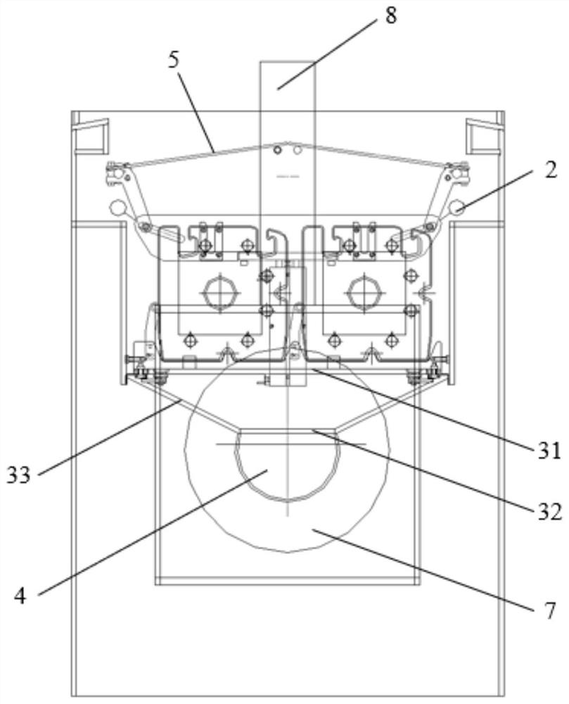
[0027] The embodiment of this specification provides a negative pressure drying device, which includes a main tank body and an exhaust air assembly, wherein the exhaust air assembly is used to form a negative pressure in the main tank body, and the exhaust air assembly can be used to store the to-be-dried parts 9 at room temperature. The surface dehydration can effectively reduce the surface moisture, avoid the generation of watermarks and other contamination, and can cooperate with other previous tanks to achieve low-temperature slow-pull cleaning, and can greatly shorten the drying time in the subsequent drying process; For example, in a possible embodiment of this specification, the negative pressure drying device is used for drying silicon wafers in electric solar cells. In the flower basket of the silicon wafer, the air exhaust component sucks the water on the surface of the silicon wafer to move downward with the airflow, so as to ensure that the watermark on the surface ...


PUM


Abstract

The invention discloses a negative pressure drying device which comprises a main tank body and an exhaust assembly. The main tank body comprises a standing area, a plurality of inflation pipelines located above the standing area, two groups of flow uniformizing plate assemblies located below the standing area, and an air duct located below the flow uniformizing plate assemblies; the exhaust assembly is located at one end of the air duct and used for forming negative pressure in the main tank body; the standing area is used for placing parts to be dried; each flow uniformizing plate assembly comprises a first flow uniformizing plate and a second flow uniformizing plate which are arranged in a double-layer mode; each second flow uniformizing plate is located below the corresponding first flow uniformizing plate; the area of each first flow uniformizing plate is larger than the area of the corresponding second flow uniformizing plate; the first flow uniformizing plates communicate with the standing area; the second flow uniformizing plates communicate with the air duct; and holes formed in the two second flow uniformizing plates are different. According to the negative pressure dryingdevice provided by the invention, surface dehydration can be conducted at the normal temperature through negative pressure, and then hot air drying is conducted, so that liquid adsorption on the surface of the parts to be dried can be effectively removed, watermarks or dirt is avoided, the performances of the parts to be dried are improved, and meanwhile, the drying time can be shortened.

Description

technical field [0001] The invention relates to the technical field of solar cell manufacturing, in particular to a negative pressure drying device. Background technique [0002] Solar cell, also known as solar chip or photovoltaic cell, is a kind of optoelectronic semiconductor sheet that uses sunlight to generate electricity directly, and directly converts light energy into electrical energy through the photoelectric effect or photochemical effect; with the continuous development of the solar cell industry, crystalline silicon solar cells It has always been the absolute mainstream product in the photovoltaic market. As the basic material of crystalline silicon solar cells, the quality of silicon wafers has a very important impact on the performance of the cells; on the one hand, the internal defects and impurities of the silicon wafers will directly affect the efficiency and stability of the cells; on the other hand, the appearance of the silicon wafers Defects and surfac...

Claims


Application Information

Patent Timeline
Patent Type & Authority Applications(China)
IPC IPC(8): F26B9/06F26B21/00F26B21/14F26B25/00F26B25/12F26B25/18
CPCF26B9/06F26B21/14F26B21/003F26B25/18F26B25/002F26B25/12
Inventor 张淋梁先东
Owner 苏州宝馨智能制造有限公司
Learn More