Magnetic induction coil module

A technology of magnetic induction coils and modules, applied in the direction of transformer/inductor coil/winding/connection, transformer/inductor parts, electrical components, etc., can solve the problems of low current resistance, difficult automation process, prone to errors, etc. Achieve the effect of reducing production costs, reducing blind connections, and improving reliability

Pending Publication Date: 2021-03-26
PIN SHINE INDAL
View PDF2 Cites 0 Cited by
  • Summary
  • Abstract
  • Description
  • Claims
  • Application Information

AI Technical Summary

Problems solved by technology

[0006] 1. It should be noted that using PCB printing technology to manufacture conductive coil patterns to become the primary and secondary coils of transformers is complicated, the current resistance is small, and the cost burden is high. It is difficult for the manufactured products to have a price competitive advantage in the market.
[0007] 2. Coating insulating varnish on the surface of the two groups of coils to isolate each other is difficult to meet the safety requirements of transformer manufacturing, and it is easy to cause damage to the transformer during operation; especially used in AC-to-DC (AC-DC) ) transformer, due to the large voltage difference at the alternating current (AC) power supply terminal, the isolation between the primary coil and the secondary coil must have a certain safety distance in terms of specifications
[0008] 3. In the prior art of No. CN201138608 Figure 7 And in the transformer disclosed in FIG. 8, when a group of primary coils 5A and two groups of secondary coils 4A, 6A are assembled with the magnetic core M1, the central magnetic conducting column of the magnetic core M1 must pass through each group of coils pre-prepared. Therefore, the alignment of these coil assembly holes must be very precise, otherwise it will cause difficulties in assembly, or cause the gap between the coil and the magnetic core to be too large
[0011] 1. There is no isolation design with a safe distance between the flat coils. As mentioned above, even if a layer of insulating varnish is applied on the surface of each group of coils as isolation, it is difficult to meet the requirements of transformer safety regulations, especially for connecting the market. Electric transformer, due to the large voltage difference at the power supply end, it is easy to cause damage to the transformer during operation
[0012] 2. Each group of coils is an independent unit and component. When assembling with the magnetic core, the central magnetic guide column of the magnetic core must pass through the assembly holes reserved on each group of coils in sequence, so the assembly holes of these coils Alignment must be very precise, which not only increases the difficulty of assembly and is prone to failure, but also wastes man-hours, and it is even more difficult to introduce automated processes, which is not conducive to a large number of production operations
[0013] 3. The plurality of conductive needles are pre-fixed on an independent base (base), and the wire ends of each coil, whether primary or secondary, must be connected to each conductive needle one by one for conduction. If the coil The higher the number of connections (this is related to the turn ratio of the primary and secondary coils), it is bound to affect the production effect. Obviously, the more the number of connections, the more prone to errors, such as blind connection or wrong connection, which will result in failure rate. increase

Method used


Image

  • Magnetic induction coil module
  • Magnetic induction coil module
  • Magnetic induction coil module

Examples


Embodiment Construction

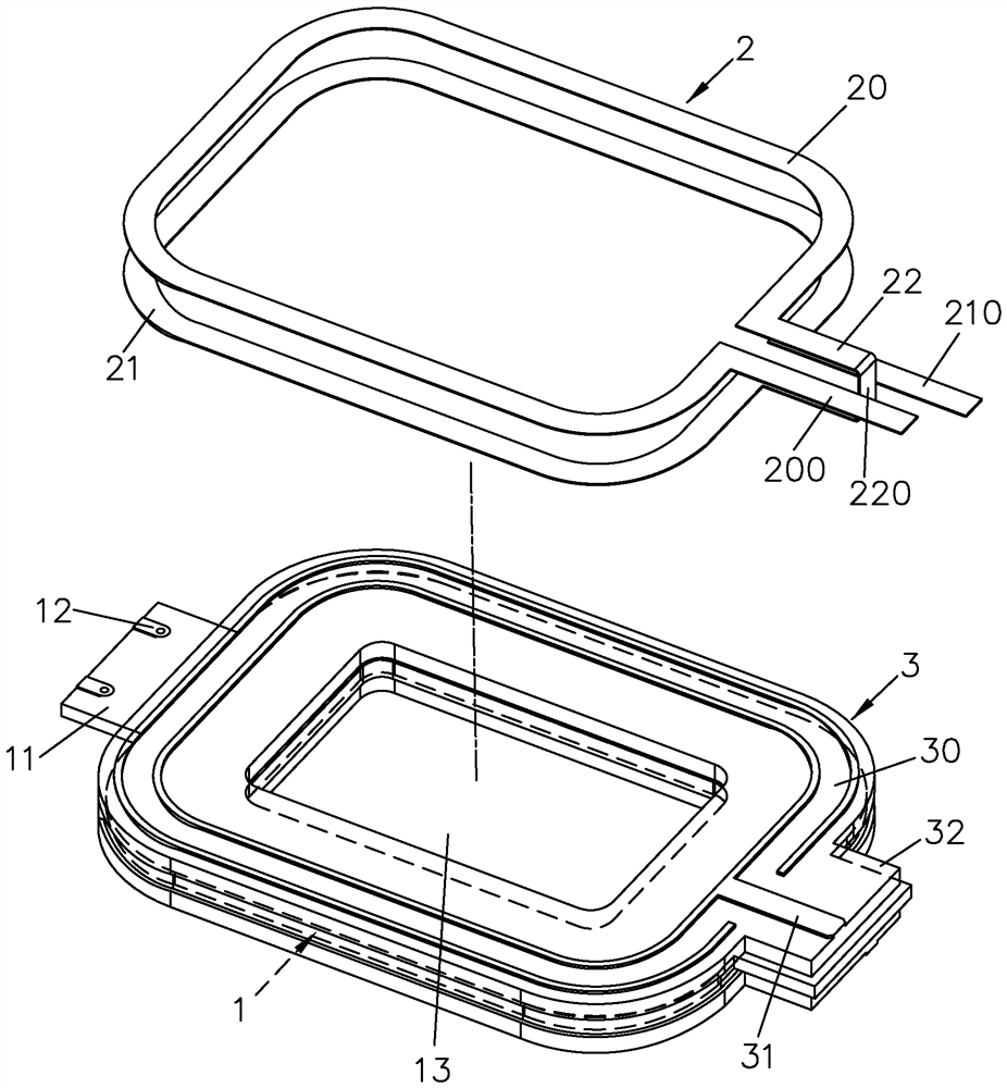
[0038] The invention is a coil module, which can be applied to magnetic induction elements such as inductors or transformers.

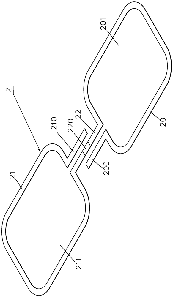
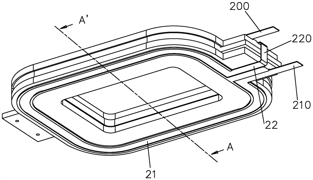
[0039] Please also refer to Figure 1 to Figure 5 , the present invention includes a first set of coils 1 and a second set of coils 2, wherein the first set of coils 1 has a first isolation layer 3 outside, and the second set of coils 2 is positioned on the first set of coils in a sandwiching manner. 1 on isolation layer 3, becomes as image 3 and Figure 4 The coil module shown.

[0040] In preferred embodiments disclosed in the present invention, such as figure 1 and Figure 5 As disclosed, the first set of coils 1 is made by disposing a conductive pattern 10 on an insulating substrate 11, for example, by disposing the conductive pattern 10 in the PCB through a printed circuit board hereinafter referred to as PCB manufacturing technology. The first group of coils 1; or, directly laying the conductive pattern 10 on the insulating substrate 11 t...


PUM


Abstract

The invention provides a magnetic induction coil module, which comprises a coil module consisting of a first group of coils and a second group of coils, a first isolation layer is coated on the firstgroup of coils, the second group of coils is a flat coil and is provided with an open first loop body, so that two end parts which are not contacted with each other are formed, one end part is provided with a first conduction part which protrudes towards the outside of the first loop body, the other end part is provided with a connecting end, the connecting end integrally extends outwards to forman open second loop body, the tail end of the second loop body is provided with a second conduction part which protrudes outwards, a turning part wraps the connecting end, the second loop body and thefirst loop body are oppositely arranged in the same direction through the turning part, and the second group of coils are positioned on the first isolation layer in a clamping manner, so that the assembly efficiency is improved, and the reject ratio of products is reduced.

Description

technical field [0001] The invention relates to a coil module, in particular to a magnetic induction coil module used for inductors and transformers. Background technique [0002] For example, the framework of a magnetic induction coil module such as a transformer includes at least two sets of independent coils (coils), the so-called "primary coils" and "secondary coils". The coil (turn) ratio is used to convert the voltage value. [0003] In practical applications, the transformer is usually built on an independent insulating base (base), and the insulating base is pre-distributed with a plurality of conductive pins (pins) or contact legs connected to the coil to form a transformer assembly. It is connected to the external circuit through these conductive pins or contact pins, so that the transformer assembly is connected to the external circuit, and at the same time, the insulating base is used as a signal isolation to avoid interference. [0004] In order to meet the mi...

Claims


Application Information

Patent Timeline
IPC IPC(8): H01F27/28H01F27/30H01F27/32
CPCH01F27/28H01F27/2804H01F27/2871H01F27/303H01F27/323H01F27/324
Inventor 林治宏张坤全
Owner PIN SHINE INDAL
Why Eureka
Try Eureka