Optical element and optical module

A technology for optical components and optical modules, applied in the field of optics, can solve the problems of assembly and adjustment deviation, high economic cost, and unsuccinct optical structure design.

Pending Publication Date: 2021-03-30
FOCUSLIGHT TECH
View PDF0 Cites 1 Cited by
  • Summary
  • Abstract
  • Description
  • Claims
  • Application Information

AI Technical Summary

Problems solved by technology

[0003] The prior art realizes the above-mentioned functions through the combination of multiple optical elements, which will lead to uns

Method used


Image

  • Optical element and optical module
  • Optical element and optical module
  • Optical element and optical module

Examples


Embodiment 1

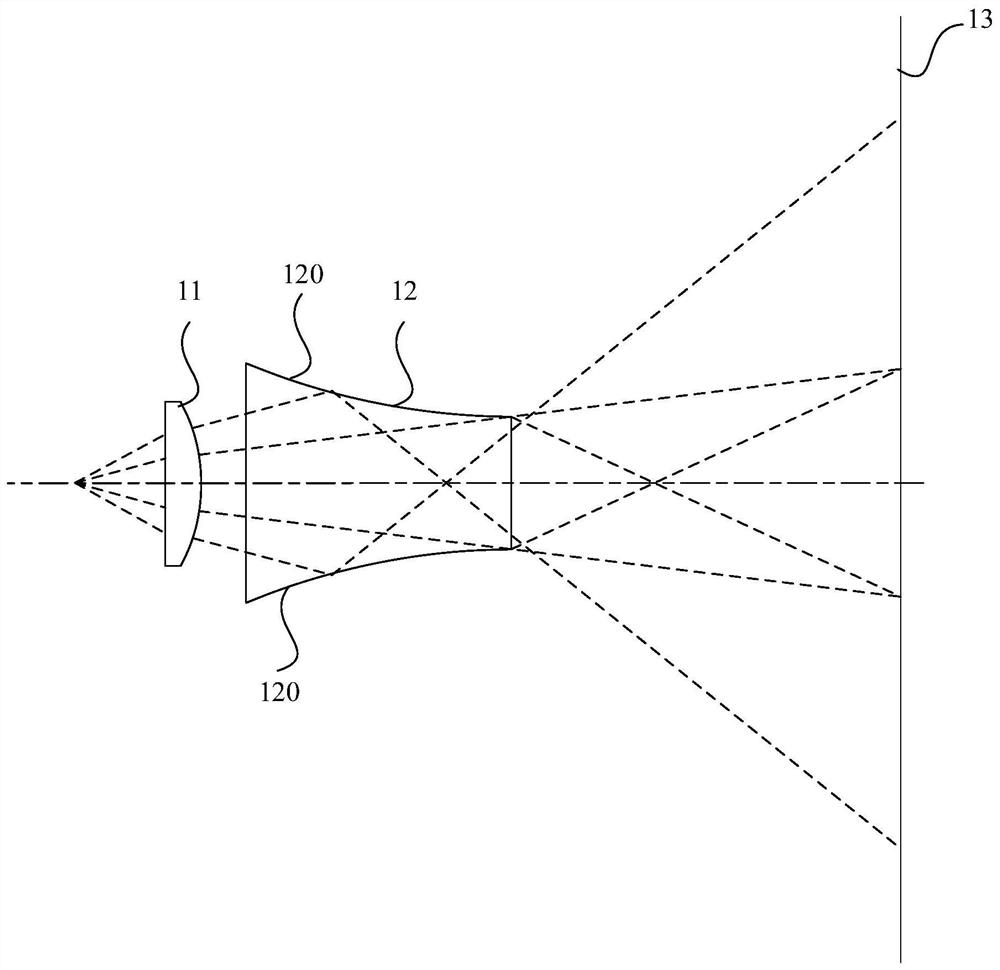
[0071] Such as figure 1 As shown, it includes semiconductor laser light source, compression mirror 11 or beam expander mirror and the first reflective surface 120 is the optical element 12 (optical waveguide) of concave arc, and the exit end is a small end (two first reflective surfaces 120 surface type is a reverse To a paraboloid or a hyperboloid, the surface type is corrected into an aspherical surface through a high-order term coefficient).

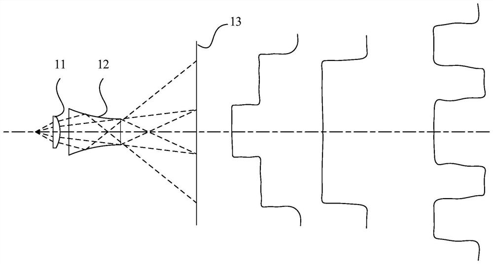
[0072] The laser beam emitted by the semiconductor laser passes through the slow axis compression mirror 11 (only the spot size is compressed), and exits into the side arc-shaped optical waveguide. A reflective surface 120 arc surface type total reflection or reflective exit, forming figure 2 Spot energy distribution shown. The arc surface type is a reverse paraboloid or a hyperboloid or a high-order aspheric surface of both basic surface types. The outgoing light beams on both sides form a certain angle with the middle light beam...

Embodiment 2

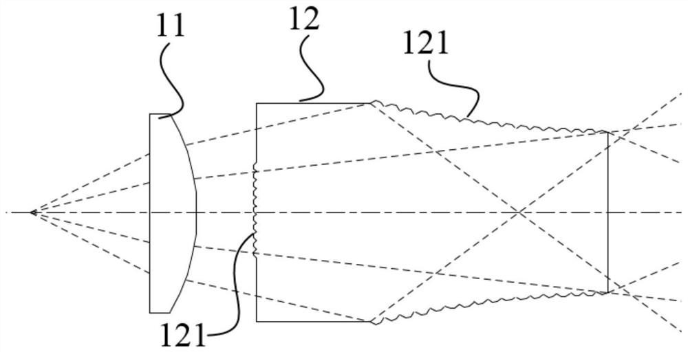
[0074] The difference between this embodiment and the first embodiment is that the first reflective surface 120 is Figure 5 In the convex arc shape shown, the surface type of the first reflecting surface 120 is a forward parabola or a hyperboloid, and the surface type is corrected to an aspheric surface through the high-order coefficient, forming Figure 6 Spot energy distribution shown. The arc of the first reflecting surface 120 has Figure 7 The shown microstructure 121, the microstructure 121 is a concave surface, concave to the main optical axis, forming Figure 8 Spot energy distribution shown.

Embodiment 3

[0076] The difference between this embodiment and the first embodiment is that the first reflective surface 120 is Figure 9 As shown in the convex arc shape, the exit end is a large end, and the surface type of the first reflecting surface 120 is a reverse paraboloid or a hyperboloid, and the surface type is corrected to an aspherical surface through the coefficient of the high-order term, forming Figure 10 Spot energy distribution shown. The arc of the first reflecting surface 120 has Figure 11 As shown in the microstructure 121, the microstructure 121 is a concave surface, concave toward the main optical axis.


PUM


Abstract

The embodiment of the invention provides an optical element and an optical module, and belongs to the technical field of optics. The optical element is provided with an incident surface, an emergent surface, two first reflecting surfaces which are symmetrically arranged along a main optical axis in a fast axis direction, and two second reflecting surfaces which are symmetrically arranged along themain optical axis in a slow axis direction; light beams emitted by a light source respectively enter the main optical axis and the two first reflecting surfaces and/or the two second reflecting surfaces through the incident surface and then are emitted through the emergent surface so as to form a superposed light spot; light beams emitted by the light source respectively enter the main optical axis and the two first reflecting surfaces, or the two second reflecting surfaces, or the two first reflecting surfaces and the two second reflecting surfaces through the incident surface and then are emitted through the emergent surface; the light beams are divided into a plurality of parts; the light beams are rearranged, so that the light beam distribution characteristics are changed; the light beams are homogenized; light spot superposition is realized; no limitation and requirements are exposed on the light source; and light spots are changed according to different light sources. The optical element has the advantages of small size, compact structure and low cost. Light spot forms are diversified, flexibility is high, and different requirements are met.

Description

technical field [0001] The present application relates to the field of optical technology, in particular, to an optical element and an optical module. Background technique [0002] In the prior art, there is no optical element that can realize the following four functions at the same time: (1) change the beam distribution characteristics; (2) cut the beam and rearrange the beam; (3) superimpose the beam in different application scenarios; (4) beam Homogenize. [0003] In the prior art, the above-mentioned functions are realized through the combination of multiple optical elements, which leads to unsuccinct optical structural design, deviation in assembly and adjustment, high economic cost, and other disadvantages of system combination. Contents of the invention [0004] The purpose of the present application is to provide an optical element capable of changing beam distribution characteristics; cutting beams and rearranging beams; superimposing beams in different applicat...

Claims


Application Information

Patent Timeline
IPC IPC(8): G02B27/09
CPCG02B27/0927G02B27/0983
Inventor 蔡磊
Owner FOCUSLIGHT TECH
Why Eureka
Try Eureka