Laser engraving device

A laser engraving and mounting plate technology, applied in laser welding equipment, fixed filter element filters, dispersed particle filtration, etc., can solve the problems of dust pollution, poor dust absorption effect, inconsistent clamping force, etc., to improve product quality, The effect of ensuring good health and reducing product errors

Inactive Publication Date: 2021-04-09
SUZHOU MIKE LASER TECH SERVICE CO LTD
View PDF0 Cites 1 Cited by
  • Summary
  • Abstract
  • Description
  • Claims
  • Application Information

AI Technical Summary

Problems solved by technology

[0003] During the process of laser engraving on the product, a lot of dust will be generated. These dusts are easy to flow and disperse with the airflow, which is easy to cause dust pollution. The existing dust removal method basically adopts the lower absorption dust removal method, which is very easy to block. The dust removal effect is poor. The dust removal effect of the current laser engraving dust removal device is poor. The device uses the restoring force of the spring to realize the extension and retraction of the clamping jaws
It includes two clamping claws, one of which is a fixed structure and the other can move relatively. This structure is inconvenient to operate and the adjustment range is limited; Realize the synchronous equidistant movement of the two clamping jaws, which brings inconvenience to the operation, and there is a phenomenon that the clamping force is inconsistent when the size is different; the other structure is to use the involute chuck structure to control the movement of the two clamping jaws, but The structure needs to be enlarged horizontally and vertically to achieve a larger moving stroke. The volume of the involute chuck limits the range of clamping claw adjustment. The volume is too large and it is inconvenient to use. Therefore, it is urgent to invent a laser engraving device. , to solve the problems raised in the above background technology

Method used


Image

  • Laser engraving device
  • Laser engraving device
  • Laser engraving device

Examples


Embodiment Construction

[0024] The following will clearly and completely describe the technical solutions in the embodiments of the present invention with reference to the accompanying drawings in the embodiments of the present invention. Obviously, the described embodiments are only some, not all, embodiments of the present invention. Based on the embodiments of the present invention, all other embodiments obtained by persons of ordinary skill in the art without making creative efforts belong to the protection scope of the present invention.

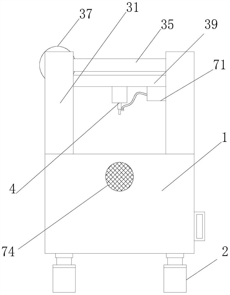
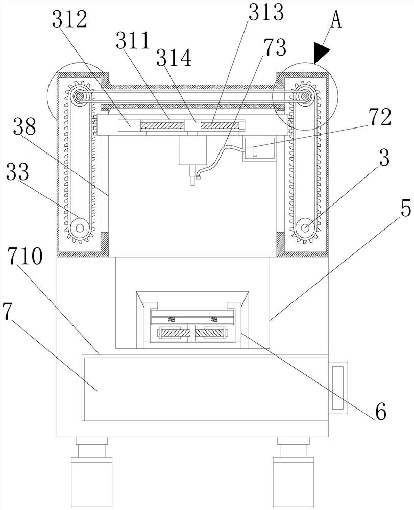
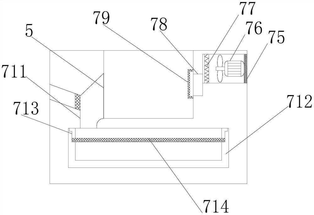
[0025] see Figure 1-5 , the present invention provides a technical solution: a laser engraving device, including an engraving table 1, an engraving adjustment mechanism 3, a product clamping mechanism 6, and a cleaning and chip removal mechanism 7, the engraving table 1 is arranged horizontally, and the bottom of the engraving table 1 is vertically arranged There are supporting feet 2, the top surface of the supporting feet 2 is fixedly connected with the bot...


PUM


Abstract

The invention relates to the technical field of laser engraving devices, and discloses a laser engraving device which comprises an engraving table, an engraving adjusting mechanism, a product clamping mechanism and a cleaning and scrap removing mechanism. The engraving table is horizontally arranged, and the engraving adjusting mechanism is arranged above the engraving table. According to the laser engraving device, through the arrangement of the product clamping mechanism, when two clamping plates act synchronously, the clamping or loosening action is achieved at a high speed, the clamping range is large, and use is convenient; through the arrangement of the cleaning and scrap removing mechanism, a working face is subjected to dust removing and scrap removing at the same time in a water cleaning mode and a gas cleaning mode, the cleaning effect is rapidly achieved; through the arrangement of a third filtering plate, waste scraps are separated from waste water, later recycling treatment is facilitated; through the arrangement a third motor and a heating net, a product carving face is dried; and through the arrangement of the engraving adjusting mechanism, synchronous movement of the left end and the right end of a movable plate is guaranteed through synchronous movement of a toothed chain, the product engraving precision is higher, and the product quality is improved.

Description

technical field [0001] The invention relates to the technical field of laser engraving devices, in particular to a laser engraving device. Background technique [0002] The laser engraving machine can improve the engraving efficiency, make the surface of the engraved place smooth and round, rapidly reduce the temperature of the engraved non-metallic material, and reduce the deformation and internal stress of the engraved object; according to the different laser sources, it can be divided into carbon dioxide and non-metallic materials. Metal laser engraving machines and optical fiber metal engraving machines, carbon dioxide non-metallic laser engraving machines generally use glass laser tubes in China, and some high-end laser engraving machines use carbon dioxide metal radio frequency tubes. [0003] During the process of laser engraving on the product, a lot of dust will be generated. These dusts are easy to flow and disperse with the airflow, which is easy to cause dust pol...

Claims


Application Information

Patent Timeline
Patent Type & Authority Applications(China)
IPC IPC(8): B23K26/362B23K26/142B23K26/70B01D29/03B01D46/10B01D46/12
CPCB01D29/03B01D46/10B01D46/12B23K26/362B23K26/142B23K26/702
Inventor 熊春霞李陶
Owner SUZHOU MIKE LASER TECH SERVICE CO LTD
Why Eureka
Try Eureka