Immersion liquid supply device
A supply device and liquid immersion technology, which is applied in the exposure device, optics, and instruments of the photoplate making process, can solve the problems of not taking away and removing pollutants in time, interfering with the exposure light path, etc., achieving stable optical properties, ensuring exposure quality, and enhancing exposure. The effect of the uniform effect
- Summary
- Abstract
- Description
- Claims
- Application Information
AI Technical Summary
Problems solved by technology
Method used
Image

Examples
Embodiment 1
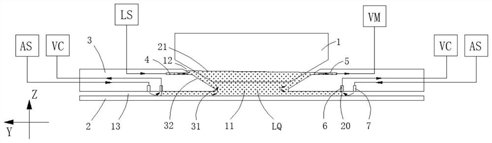
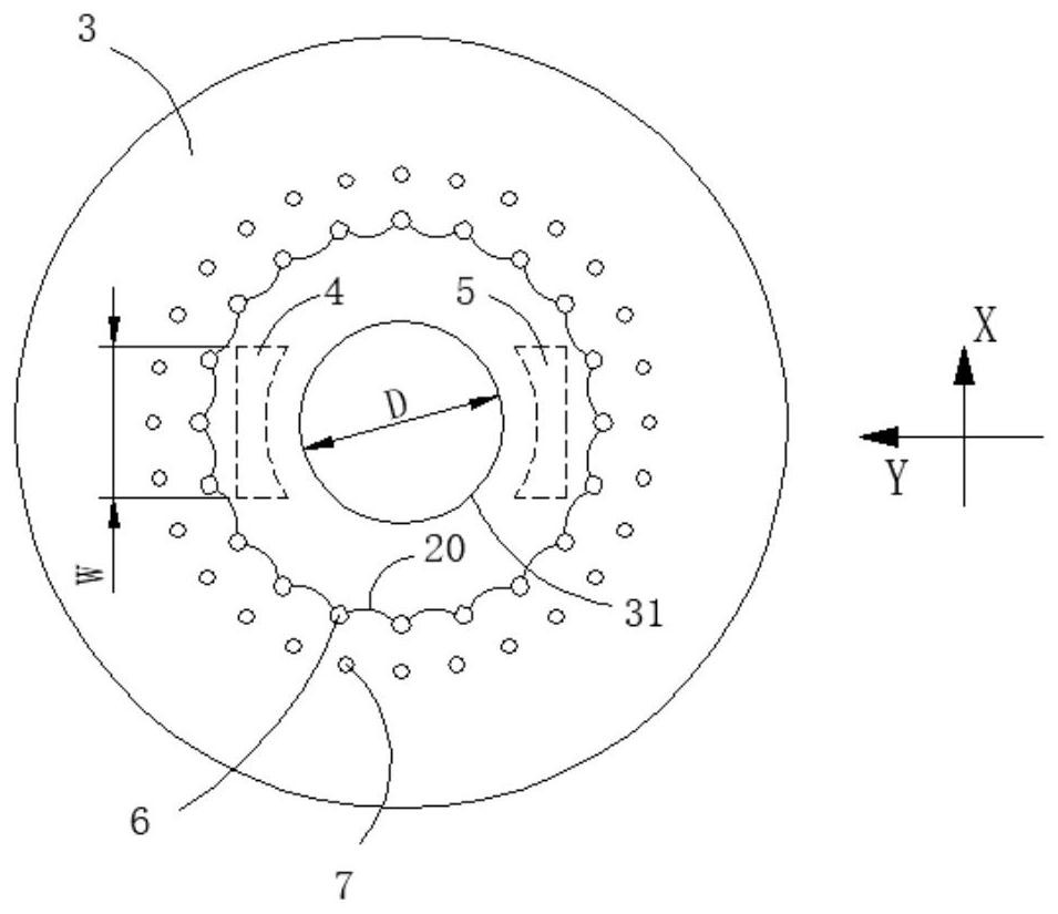
[0028] Such as figure 1 , figure 2 and image 3 As shown, an immersion liquid supply device 3 includes a surrounding surface 32 surrounding the terminal objective lens; the surrounding surface 32 has a main liquid injection port 4 through which immersion liquid is supplied to the immersion flow field. Since the substrate mainly performs a scanning motion in the X direction and a stepping motion in the Y direction relative to the immersion liquid supply device 3, during the scanning motion of the substrate, the exposure laser beam projects an integrated circuit pattern to the substrate; in order to improve It is expected that the rate of scanning motion is high; the substrate moving at a high scanning motion rate will have a strong pulling effect on the immersion liquid, which will disturb the flow direction of the immersion liquid in the immersion flow field. On the side of the surrounding surface 32 opposite to the main liquid injection port 4, the main suction outlet 5 is...
Embodiment 2
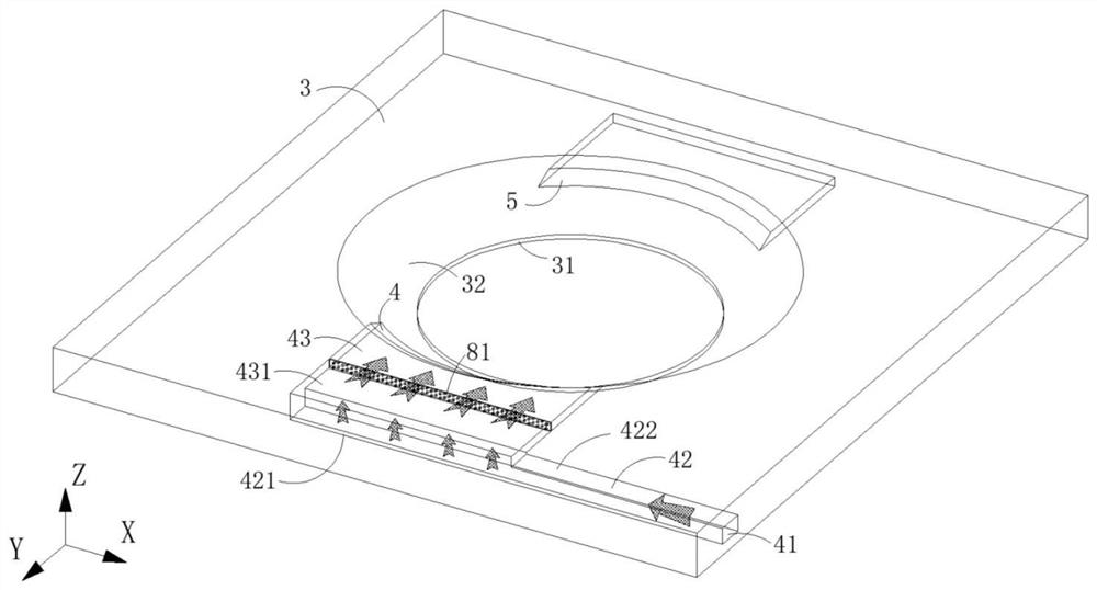
[0034] Such as Figure 4 As shown, the bottom surface 421 of the drainage flow path has an inclined section, and the end of the inclined section away from the main liquid inlet interface 41 is farther from the bottom surface 431 of the outlet flow path. The remaining implementation modes are the same as the first embodiment.
[0035] Due to the inertia of the immersion liquid flowing in the drainage channel 42, the end away from the main liquid inlet port 41 (the end in the -X direction) will be blocked by the wall and accumulate the immersion liquid, which will increase the local pressure and cause the main liquid injection port 4 There is a larger immersion liquid flow rate on the -X side; the bottom surface 421 of the drainage flow path is set to have a larger volume at the -X end, which can accommodate more accumulation of immersion liquid, thereby alleviating the inflow and outflow flow caused by the flow inertia of the immersion liquid The problem of uneven traffic afte...
Embodiment 3
[0037] Such as Figure 5 As shown, the immersion liquid supply device 3 also includes a second orifice plate 82, the second orifice plate 82 is arranged at the junction of the drainage flow path 42 and the outflow flow path 43, and the second orifice plate 82 is parallel to the bottom surface 431 of the outflow flow path Set, there are evenly distributed through small holes on the second orifice plate 82 . The remaining implementation modes are the same as the first embodiment.
[0038] The second orifice 82 relatively isolates the drainage channel 42 from the outlet channel 43. On the one hand, it can enhance the flow uniformity of the immersion liquid flowing from the drainage channel 42 into the outlet channel 43. On the other hand, it can also play a role in isolation and drainage. The effect of the pressure pulsation of the flow path 42 and the outflow flow path 43 cuts off the mutual influence path of the pressure pulsation from the immersion flow field and the immersio...
PUM
 Abstract
Description
Claims
Application Information
 - R&D
- Intellectual Property
- Life Sciences
- Materials
- Tech Scout
- Unparalleled Data Quality
- Higher Quality Content
- 60% Fewer Hallucinations
Browse by: Latest US Patents, China's latest patents, Technical Efficacy Thesaurus, Application Domain, Technology Topic, Popular Technical Reports.
© 2025 PatSnap. All rights reserved.Legal|Privacy policy|Modern Slavery Act Transparency Statement|Sitemap|About US| Contact US: help@patsnap.com