Intelligent path planning device and method for industrial mechanical arm
A path planning and industrial machinery technology, applied in the direction of manipulators, program-controlled manipulators, manufacturing tools, etc., can solve the problems of reduced industrial production efficiency, affecting processing accuracy, efficiency, and defective products, so as to improve processing quality and efficiency, Guarantee the effect of processing quality
- Summary
- Abstract
- Description
- Claims
- Application Information
AI Technical Summary
Problems solved by technology
Method used
Image

Examples
Embodiment Construction
[0035] The technical solutions of the present invention will be further described below in conjunction with the accompanying drawings and through specific implementation methods.
[0036] Wherein, the accompanying drawings are only for illustrative purposes, showing only schematic diagrams, rather than physical drawings, and should not be construed as limitations on this patent; in order to better illustrate the embodiments of the present invention, some parts of the accompanying drawings will be omitted, Enlargement or reduction does not represent the size of the actual product; for those skilled in the art, it is understandable that certain known structures and their descriptions in the drawings may be omitted.
[0037] The present invention specifically adopts the following technical solutions to achieve the above-mentioned technical purpose:
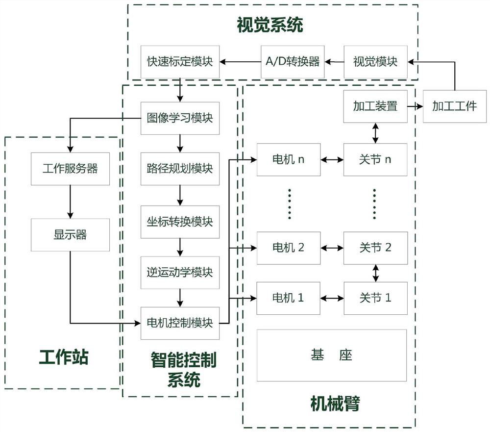
[0038] Such as figure 1 As shown in the figure, an intelligent path planning device for an industrial manipulator includes a proce...
PUM
 Abstract
Description
Claims
Application Information