Water drive logging device

A well logging and water flooding technology, applied in the direction of measurement, borehole/well components, and production fluid, etc., can solve problems affecting construction efficiency, large lifting resistance, and complicated control mechanism, so as to improve construction production efficiency and reduce Lift up the resistance and expand the effect of the use scene

Active Publication Date: 2021-04-13
BEIJING ZEBANON SCI & TECH
View PDF10 Cites 0 Cited by
  • Summary
  • Abstract
  • Description
  • Claims
  • Application Information

AI Technical Summary

Problems solved by technology

When logging in water injection wells, hydraulic force can be used to push the instrument string to the target layer for detection. In related technologies, when the instrument string is pushed, a short section with a larger diameter can be connected to the instrument string to reduce water flow channels, so as to achieve The purpose of hydraulically pushing the instrument string, but in this way, the risk of the instrument string being stuck is greater, and when the instrument string is lifted up, if the water injection displacement is not reduced, the lifting resistance will be very large. If the water injection displacement is reduced, then Need to shut down and stop production, affecting normal production
Another method is to insert a scalable rubber bladder short joint in the instrument string, and reduce the water flow channel by driving the bladder to expand, so as to achieve the purpose of hydraulically pushing the instrument string. However, this method can be solved by shrinking the rubber bladder However, the rubber bladder is severely worn underground and needs to be replaced frequently. The maintenance of the instrument is very inconvenient and affects the construction efficiency.
Moreover, the control mechanism that controls the expansion and contraction of the skin bag is relatively complicated, resulting in a relatively large volume of the instrument and limited use scenarios

Method used


Image

  • Water drive logging device
  • Water drive logging device
  • Water drive logging device

Examples


Embodiment 1

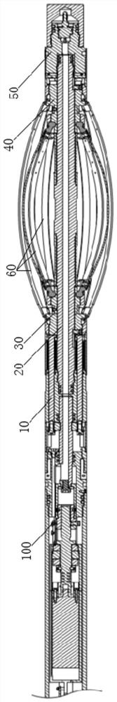
[0043] See figure 1 , a water flooding logging device, comprising: a Hall element 100 , a driving assembly 10 , a central rod 20 , a first connection assembly 30 , a second connection assembly 40 , a fixed sleeve 50 and a plurality of metal strip assemblies 60 . The Hall element 100 is arranged on the driving assembly 10 , and the Hall element 100 is used for sending the working signal of the driving assembly 10 . The working signal can control the shutdown of the driving motor 11 of the driving assembly 10 . The driving assembly 10 is connected with one end of the central rod 20 and the first connecting assembly 30 , and the driving assembly 10 is used to drive the first connecting assembly 30 to slide axially on the central rod 20 . The first connection assembly 30 is sheathed on the center rod 20 , and the first connection assembly 30 is slidably connected with the center rod 20 . In this embodiment, the driving assembly 10 can drive the first connecting assembly 30 to sl...

Embodiment 2

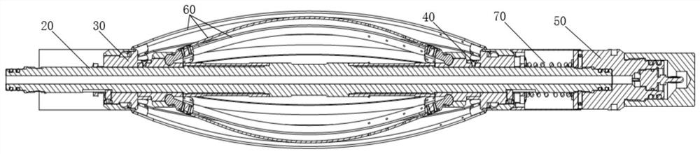
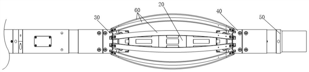
[0057] Such as figure 2 and Figure 4 As shown, this embodiment is based on the first embodiment and further defines a layer structure in which a plurality of metal strip assemblies 60 are surrounded by multiple layers. A plurality of metal strip assemblies 60 may form a multi-layer structure. A plurality of metal strip assemblies 60 of each layer are sequentially arranged around the circumferential direction of the central rod 20 . The first connection assembly 30 includes a plurality of first sliding sleeves 31 . The second connection assembly 40 includes a plurality of second sliding sleeves 41 . The metal strip assembly 60 of each layer is connected with a first sliding sleeve 31 and a second sliding sleeve 41 . In the structure of one layer, a first sliding sleeve 31 is connected to one end of multiple metal strip assemblies 60 , and a second sliding sleeve 41 is connected to the other ends of multiple metal strip assemblies 60 . A plurality of first sliding sleeves...

Embodiment 3

[0076] Such as Figure 12 As shown, this embodiment is based on the first or second embodiment and further defines that the drive assembly 10 includes: a drive motor 11 , a lead screw 12 , a nut sleeve 13 , a push-pull assembly 14 and a housing 15 . The casing 15 is all tubular, or partly tubular, partly columnar. It can also be an integral shell structure, or can be composed of multi-section shells 15 . The shell of the driving motor 11 is fixedly connected with one end of the housing 15 . The output shaft of the driving motor 11 is fixedly connected with one end of the lead screw 12 . The screw 12 extends along the axial direction of the central rod 20 , and the screw 12 is located in the housing 15 . The nut sleeve 13 is threadedly connected with the lead screw 12 , and the nut sleeve 13 is slidably connected with the housing 15 through the stopper 16 , and the end of the nut sleeve 13 away from the driving motor 11 is connected with the push-pull assembly 14 . The limit...


PUM


Abstract

The invention discloses a water drive logging device. The water drive logging device comprises a Hall element, a drive assembly, a central rod, a first connecting assembly, a second connecting assembly, a fixing sleeve and a plurality of metal strip assemblies. The Hall element is arranged on the driving assembly; the driving assembly is used for driving the first connecting assembly to axially slide on the central rod; the first connecting assembly is slidably connected with the central rod; the second connecting assembly is slidably connected with the central rod; the fixing sleeve is fixedly connected with the other end of the central rod; and the multiple metal strip assemblies are driven by sliding of the first connecting assembly to arch outwards or reset inwards. The metal strip assemblies can arch outwards through driving of the driving assembly, the metal strip assemblies block injected driving hydraulic power to a certain extent to form certain hydraulic driving, and the hydraulic driving water drive logging device conveys an instrument string in an oil pipe. The metal strip assemblies are small in abrasion in the using process, the service life is prolonged, the metal strip assemblies can be continuously used, and the construction production efficiency is improved.

Description

technical field [0001] The invention belongs to the technical field of logging instruments, and in particular relates to a water drive logging device. Background technique [0002] With the deepening of oilfield exploration and development and the development of drilling technology, the number of horizontal wells and highly deviated wells in the oil area is increasing year by year, and the workload of horizontal well logging increases accordingly. When logging in water injection wells, hydraulic force can be used to push the instrument string to the target layer for detection. In related technologies, when the instrument string is pushed, a short section with a larger diameter can be connected to the instrument string to reduce water flow channels, so as to achieve The purpose of hydraulically pushing the instrument string, but in this way, the risk of the instrument string being stuck is greater, and when the instrument string is lifted up, if the water injection displaceme...

Claims


Application Information

Patent Timeline
IPC IPC(8): E21B43/20E21B47/00E21B47/01E21B41/00
CPCE21B43/20E21B47/00E21B47/01E21B41/00
Inventor 谢阳平黄书伟李凯
Owner BEIJING ZEBANON SCI & TECH
Why Eureka
Try Eureka