Distribution transformer for communication power system

A distribution transformer and power system technology, applied in the direction of transformer/inductor cooling, etc., can solve the problems of slow cooling oil circulation flow and high transformer temperature, achieve good heat transfer effect, less heat transfer temperature, and increase flow speed Effect

Inactive Publication Date: 2021-04-13
田甜
View PDF0 Cites 0 Cited by
  • Summary
  • Abstract
  • Description
  • Claims
  • Application Information

AI Technical Summary

Problems solved by technology

[0003] During the use of existing oil-immersed transformers, the cooling oil enters the heating elements such as windings and is continuously heated at the height of the windings. The density of the oil decreases continuously and gradually increases the upward buoyancy to flow upwards. The rising heat The oil leaves the winding and enters the radiator. After the hot oil flowing through the radiator is cooled down, it flows into the transformer box again. This kind of cooling oil circulation is achieved by relying on the density change after its own heating. The cooling oil circulation flow speed Slower, before the cooling oil in the transformer box flows to the radiator, the temperature of the cooling oil after heat exchange is higher, resulting in a higher temperature in the transformer

Method used


Image

  • Distribution transformer for communication power system
  • Distribution transformer for communication power system
  • Distribution transformer for communication power system

Examples


Embodiment Construction

[0016] The following will clearly and completely describe the technical solutions in the embodiments of the present invention with reference to the accompanying drawings in the embodiments of the present invention. Obviously, the described embodiments are only some, not all, embodiments of the present invention. Based on the embodiments of the present invention, all other embodiments obtained by persons of ordinary skill in the art without making creative efforts belong to the protection scope of the present invention.

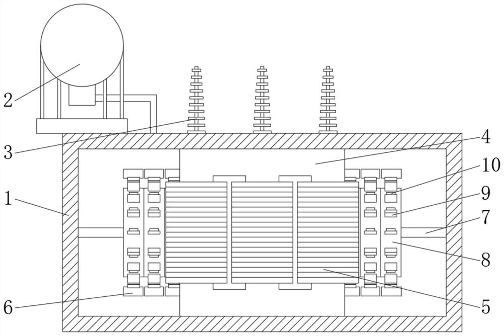
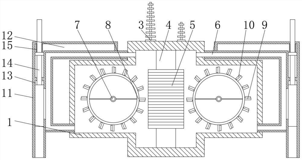
[0017] see Figure 1-4 , a distribution transformer for a communication power system, comprising a transformer box 1, an oil conservator 2 is fixedly installed on one side of the upper surface of the transformer box 1, a sleeve 3 is fixedly set in the middle of the upper surface of the transformer box 1, and the inner cavity of the transformer box 1 An iron core 4 is fixedly installed in the middle of the iron core 4, a coil 5 is wound on the outer surface of ...


PUM


Abstract

The invention relates to the technical field of power equipment, and discloses a distribution transformer for a communication power system, which comprises a transformer box. One side of the upper surface of the transformer box is fixedly provided with an oil conservator, the middle part of the upper surface of the transformer box is fixedly sleeved with a sleeve, and the middle part of the inner cavity of the transformer box is fixedly provided with an iron core. According to the distribution transformer for the communication power system, the air bag is installed at the position of the flow spreading plate, so that the air bag absorbs heat generated by the coil to expand, local pressure of cooling oil is increased, flowing of cooling liquid is improved, meanwhile, the air bag expands to generate counter-acting force on the flow spreading plate, the flow spreading ring is pushed to rotate, and the air bag rotates; cooling oil which is cooled and reinjected can firstly contact with the air bag at the bottom of the flow spreading ring for heat exchange, so that the air bag is cooled, contracted and rotated to the vicinity of the coil to expand and pressurize again, the flowing speed of the cooling oil is increased, the heat exchange temperature of the cooling oil is low, the cooling oil can be quickly cooled in the heat dissipation pipe, and the temperature of the transformer box is low.

Description

technical field [0001] The invention relates to the technical field of power equipment, in particular to a distribution transformer for a communication power system. Background technique [0002] Distribution voltage device refers to a static electrical device used in power distribution system to convert AC voltage and current according to the law of electromagnetic induction to explain AC power. For several devices with different voltages, when the primary winding is supplied with alternating current, alternating magnetic flux is generated, and the alternating magnetic flux passes through the magnetic conduction of the iron core, and the alternating electromotive force is induced in the secondary winding, and the secondary induction The level of electromotive force is related to the number of primary and secondary winding miscellaneous books, that is, the voltage is proportional to the number of turns. The mainstream energy-saving distribution transformers mainly include en...

Claims


Application Information

Patent Timeline
Patent Type & Authority Applications(China)
IPC IPC(8): H01F27/14
CPCH01F27/14
Inventor 不公告发明人
Owner 田甜
Why Eureka
Try Eureka