Auxiliary turnover device for steel member welding

A technology for flipping devices and steel components, applied in auxiliary devices, welding/cutting auxiliary equipment, welding equipment, etc., can solve the problems of large footprint, troublesome manual positioning operation, rough positioning, etc., to reduce the occupied area and improve Operational safety, length reduction effect

Inactive Publication Date: 2021-04-16
安徽宇艳智能机械科技有限公司
View PDF1 Cites 5 Cited by
  • Summary
  • Abstract
  • Description
  • Claims
  • Application Information

AI Technical Summary

Problems solved by technology

[0002] H-shaped steel is an economical cross-section high-efficiency profile with more optimized cross-sectional area distribution and a more reasonable strength-to-weight ratio. It is named because its section is the same as the English letter H. H-shaped steel has strong bending resistance, simple construction, cost-saving and structural weight. Lightweight and other advantages, it has been widely used as building materials in industries such as buildings, bridges, towers, and grids. In the three-dimensional garage industry, H-shaped steel is used as the main supporting member. The top plate is mainly positioned manually during welding, which is rough and poor in consistency, and takes up more labor resources, which increases production costs. At the same time, manual positioning is cumbersome, takes a long time, and has low production efficiency. The welding quality of the shaped steel and the bottom plate needs to be turned over during welding. Because the volume and weight of the H-shaped steel are very large, it is very difficult to turn over the H-shaped steel during welding. At present, manual methods are often used to turn over the H-shaped steel. Crane operation, not only low work efficiency, cumbersome operation, but also requires many operators, poor safety, prone to accidents
[0003] When using the existing auxiliary turning device for steel member welding, it is necessary to use a crane to move the workpiece to the inside of the clamping mechanism in the turning device for clamping and positioning. The horizontal translation is sent to the inner side of the fixed frame. However, when the crane is lifting the long H-shaped steel, it is necessary to fix the two ends of the workpiece to ensure the stability of the workpiece during the movement. When placing the workpiece on the fixed frame For the inner side, it is necessary to untie the steel cable bound on one end of the H-shaped steel to translate one end of the workpiece into the inner side of the fixed frame. During this process, the operator needs to manually support the workpiece and untie one end of the steel cable to maintain the balance of the workpiece. Due to the long length, heavy weight and large diameter of the H-shaped steel, there is a great potential safety hazard when it is supported by manpower, and the workload of the operator is also not low; Therefore, the space requirements for the device are relatively high. The horizontal area of ​​the operating space where the device is placed must not be less than the length of the workpiece plus the length occupied by the turning device itself. Considering the stability of the workpiece when it is clamped and turned over, the size of the workpiece The center of gravity should be located near the midpoint of the unit, thus requiring a larger footprint and being less economical

Method used


Image

  • Auxiliary turnover device for steel member welding
  • Auxiliary turnover device for steel member welding
  • Auxiliary turnover device for steel member welding

Examples


Embodiment 1

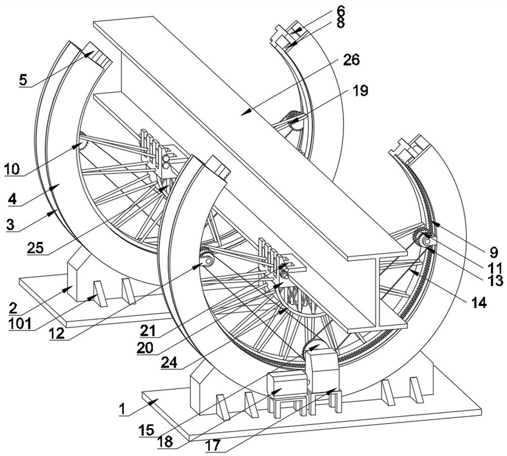
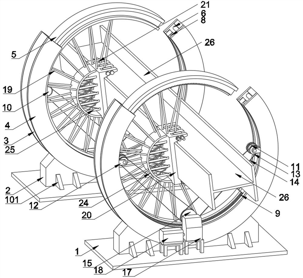
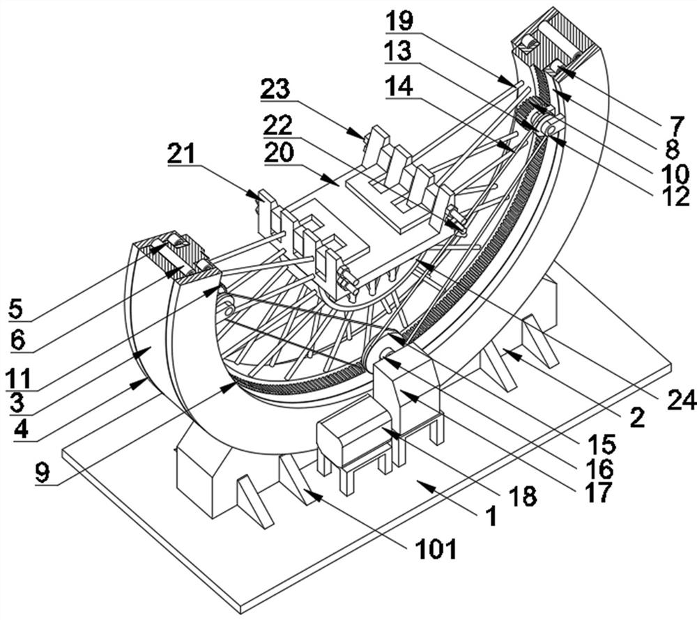
[0027] see Figure 1-Figure 7 , the present invention provides the following technical solutions: an auxiliary turning device for steel member welding, comprising a bottom plate 1, the top surface of the bottom plate 1 is fixedly installed with an outer fixing plate 3 through a fixing seat 2, and the outer fixing plate 3 The front and rear sides are fixedly connected with a side fixing plate 4, and the inner side of the side fixing plate 4 on one side of the outer fixing plate 3 is fixedly connected with an L-shaped plate 8, and the side fixing plate 4 is rotatably connected to the two ends of the outer support member 6 and the inner side. One end of the support member 7, the outer support member 6 is rotatably connected to the outer surface of the turret 5, and one side of the inner surface of the turret 5 is provided with an inner gear ring 9, and the inner gear ring 9 is meshed and connected through the shaft seat One 12 rotates the gear one 10 and gear two 11 installed on ...


PUM


Abstract

The invention belongs to the technical field of steel member machining, and particularly relates to an auxiliary turnover device for steel member welding. The device comprises bottom plates, wherein side fixed plates are fixedly connected to the front side face and the rear side face of each outer fixed plate mounted on the top face of each bottom plate through a fixing seat, the side fixing plates are rotatably connected with outer supporting pieces and inner supporting pieces, an inner gear ring is arranged at one side of the inner side face, rotationally connected with the corresponding outer supporting piece, of each rotating frame, a driven chain wheel fixedly mounted on a rotating shaft of a first gear and a second gear which are connected with each inner gear ring in a meshed mode is in transmission connection with a driving chain wheel through a transmission chain, a clamping plate and an arch frame are connected to the inner side face, at one side of the corresponding inner gear ring, of each rotating frame through supporting spokes, pressing pieces are rotationally mounted on the clamping plates through fixing shafts, and the clamping plates and the pressing pieces are provided with pin shafts in a sliding mode. An operator can vertically put down the two ends of a workpiece from the upper portions of openings of the rotating frames through crane hoisting and fix the two ends of the workpiece to the clamping plates to be clamped and fixed for turnover work, so that the occupied area of the device is effectively reduced, and operational safety is improved.

Description

technical field [0001] The invention belongs to the technical field of steel component processing, and in particular relates to an auxiliary turning device for steel component welding. Background technique [0002] H-shaped steel is an economical cross-section high-efficiency profile with more optimized cross-sectional area distribution and a more reasonable strength-to-weight ratio. It is named because its section is the same as the English letter H. H-shaped steel has strong bending resistance, simple construction, cost-saving and structural weight. Lightweight and other advantages, it has been widely used as building materials in industries such as buildings, bridges, towers, and grids. In the three-dimensional garage industry, H-shaped steel is used as the main supporting member. The top plate is mainly positioned manually during welding, which is rough and poor in consistency, and takes up more labor resources, which increases production costs. At the same time, manual ...

Claims


Application Information

Patent Timeline
Patent Type & Authority Applications(China)
IPC IPC(8): B23K37/04B23K37/00B66C13/08B23K103/04
Inventor 杨俊宇胡学友徐庆辉
Owner 安徽宇艳智能机械科技有限公司
Why Eureka
Try Eureka