

Luneberg lens antenna dielectric material as well as preparation method and application thereof
A technology of Lunberg lens antenna and dielectric material, which is applied to antennas, electrical components, etc., can solve the problems of complex process, difficult to adapt to industrialized mass production, long process of lens medium preparation, etc., and achieve uniform distribution, accurate dielectric constant, The effect of dielectric constant precision
- Summary
- Abstract
- Description
- Claims
- Application Information
AI Technical Summary
Problems solved by technology
Method used
Image

Examples
Embodiment 1
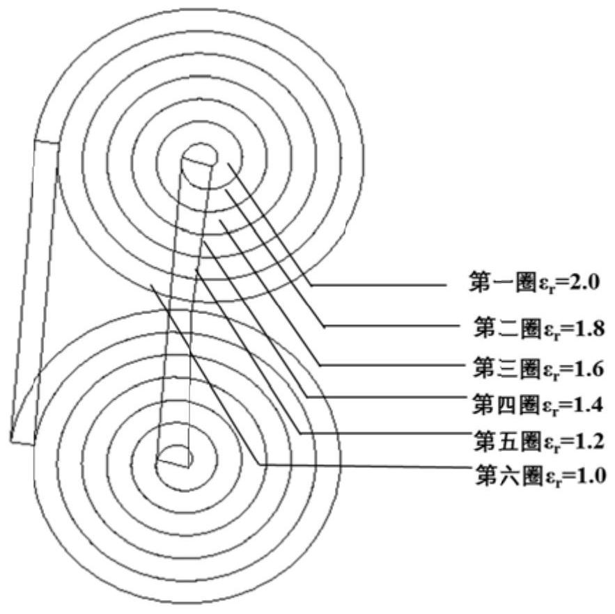
[0036] The Lunberg lens antenna dielectric material of the present embodiment comprises a polypropylene microporous foamed coiled material with a cell diameter of 1-30 μm, and the relative permittivity of the coiled material gradually decreases along the radial direction gradient, dropping from 2.0 at the center of the coiled material to The outermost layer of the coil is 1.0, and the dielectric constant gradient of the adjacent layer from the inside to the outside is 0.2.
[0037] The preparation method of the Lunberg lens antenna dielectric material of the present embodiment specifically comprises the following steps:
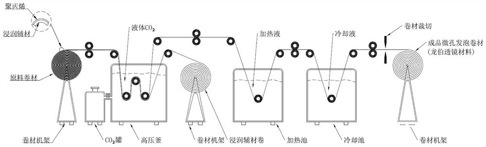
[0038] (1) Soak the polypropylene coil with non-woven paper to make the coil appear as a whole figure 1 The sandwich structure of "polypropylene-impregnation auxiliary material" shown in the autoclave forms a "supercritical carbon dioxide fluid-polypropylene substrate" homogeneous system between the liquid carbon dioxide diffused into the polypropylene membra...
Embodiment 2
[0045] The Lunberg lens antenna dielectric material of the present embodiment comprises a polystyrene microcellular foamed coiled material with a cell diameter of 10-45 μm, and the relative permittivity of the coiled material gradually decreases along the radial direction gradient, descending from 2.0 at the center of the coiled material From 1.0 to the outermost layer of the coil, the dielectric constant gradient of the adjacent layer from the inside to the outside is 0.2.
[0046] The preparation method of the Lunberg lens antenna dielectric material of the present embodiment specifically comprises the following steps:
[0047] (1) Infiltrate the polystyrene coil with non-woven paper, so that the coil as a whole presents a "polystyrene-soaked auxiliary material" sandwich structure, and the liquid carbon dioxide and polystyrene diffused into the polystyrene coil in the autoclave A homogeneous system of "supercritical carbon dioxide fluid-polystyrene substrate" is formed betwe...
Embodiment 3
[0050] The Lunberg lens antenna dielectric material of the present embodiment comprises a polycarbonate microcellular foamed coiled material with a cell diameter of 10-50 μm, and the relative dielectric constant of the coiled material gradually decreases along the radial direction gradient, descending from 2.0 at the center of the coiled material From 1.0 to the outermost layer of the coil, the dielectric constant gradient of the adjacent layer from the inside to the outside is 0.2.
[0051] The preparation method of the Lunberg lens antenna dielectric material of the present embodiment specifically comprises the following steps:
[0052] (1) Infiltrate the polycarbonate coil with non-woven paper, so that the coil as a whole presents a sandwich structure of "polycarbonate-infiltrated auxiliary material", and the liquid carbon dioxide and polycarbonate diffused into the polycarbonate coil in the autoclave A homogeneous system of "supercritical carbon dioxide fluid-polycarbonate...
PUM
| Property | Measurement | Unit |
|---|---|---|
| Cell diameter | aaaaa | aaaaa |
| Bandwidth | aaaaa | aaaaa |
| Cell diameter | aaaaa | aaaaa |
Abstract
Description
Claims
Application Information