Telescopic cutting device and heading machine

A telescopic cutting arm technology, applied in the direction of cutting machinery, slitting machinery, mining equipment, etc., can solve the problems of short telescopic stroke, large vibration of cutting head, complex structure of cutting telescopic mechanism, etc., and achieve reduction The effect of beating and strengthening support ability

Pending Publication Date: 2021-04-16
牛一村
View PDF11 Cites 2 Cited by
  • Summary
  • Abstract
  • Description
  • Claims
  • Application Information

AI Technical Summary

Problems solved by technology

[0003] The main purpose of the present invention is to provide a telescopic cutting device with a large stroke and a roadheader with a positioning and cutting function, so as to solve the problem of short telescopic stroke of the telescopic mechanism in the prior art, difficulty in gap adjustment of the telescopic mechanism, and complex structure of the cutting telescopic mechanism. , The vibration of the cutting head is large, and the reducer is prone to heat, etc.

Method used


Image

  • Telescopic cutting device and heading machine
  • Telescopic cutting device and heading machine
  • Telescopic cutting device and heading machine

Examples


Embodiment 1

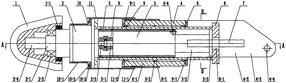
[0037] Embodiment one, with reference to the attached Figure 3 to Figure 5 , a telescopic cutting device, the carrier body is a cutting arm frame 4, the front part of the cutting arm frame 4 is provided with a cylindrical cylinder 4-1 coaxial with the motor 3, and the rear of the cutting arm frame 4 There are two groups of support lugs 4-2 at the top, each set of support lugs 4-2 is composed of two lug plates 4-3 parallel to the motor shaft, and the lug plates 4-3 are provided with hinged holes 4- 4. Two circular support guide sleeves 9 are set and fixed on the front and rear ends of the cylinder 4-1 respectively, and the inner hole of the support guide sleeve 9 is provided with a dust-proof sealing ring 9-1, and the cylindrical telescopic sleeve 5 can slide The sleeve is set between the front and rear support guide sleeves 9, a circular piston 5-1 that is slidingly fitted with the inner hole of the cylinder 4-1 is provided in the middle of the telescopic sleeve 5, and a pist...

Embodiment 2

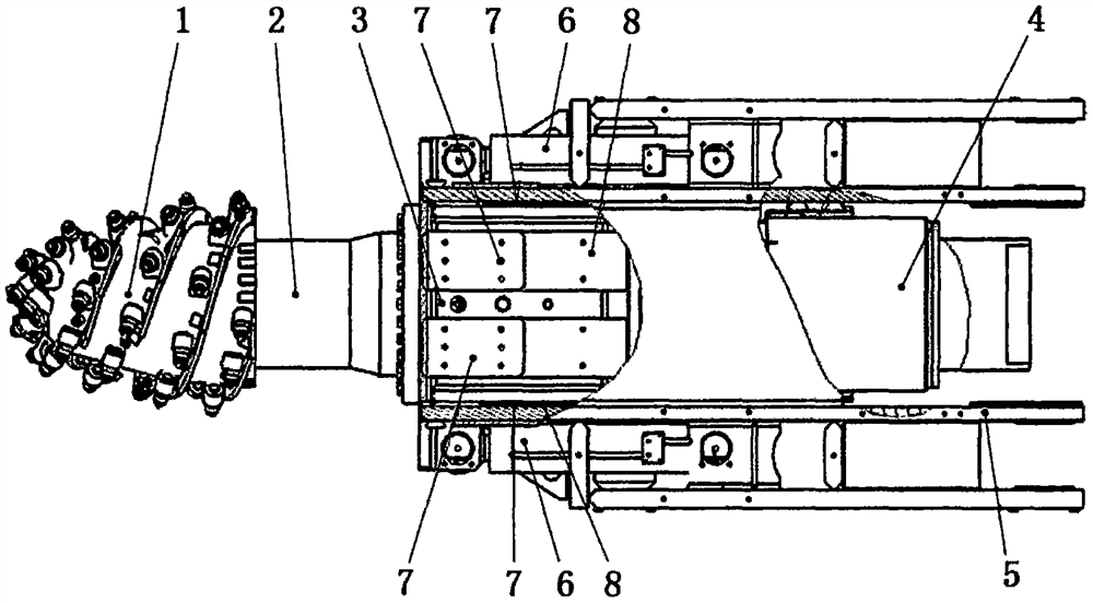
[0048] Embodiment two, referring to the attached Figure 7 to Figure 9 In this embodiment, the output shafts 2-4 of the reducer adopt a horizontal double output shaft arrangement. At this time, the output shafts 2-4 of the left and right reducers are fitted with two horizontally arranged cutting heads 1 . Adopting the arrangement of the transverse double cutting heads 1 can optimize the cutting force and reduce the lateral swing angle of the cutting boom 4 .

[0049] In order to further limit the overall length of the cutting device, in this embodiment, the connecting flange of the reducer 2 is placed in front, and the main part of the reducer 2 is also set in the telescopic sleeve 5. At this time, the connecting flange of the reducer 2 is also The ring casing 10 - 1 of the spray cooler 10 is welded and fixed to the casing of the speed reducer 2 .

[0050] The longitudinal guide rail 7 of this embodiment is an integral plate-like structure provided with a longitudinal groove-...


PUM


Abstract

The invention discloses a telescopic cutting device and a heading machine. The telescopic cutting device comprises a cutting arm support provided with a cylindrical cylinder barrel, a telescopic sleeve is sleeved with the cylinder barrel in a sliding mode, the cylinder barrel and the telescopic sleeve form a large-diameter hollow oil cylinder telescopic mechanism, a longitudinal guide rail is fixed to the cutting arm support, a guide plate matched with the longitudinal guide rail is fixed to the rear end of the telescopic sleeve, a cylindrical motor is sleeved with the telescopic sleeve, the motor, a speed reducer and a cutting head form an integral cutting power unit through the telescopic sleeve and the guide plate, liquid is supplied to a front cavity and a rear cavity of the cylinder barrel, and integral stretching and retracting of the integral cutting power unit can be achieved. The cutting device has the advantages of large telescopic stroke, simple structure, high mechanical strength and reliable work, after the heading machine is matched with the cutting device, the cutting device has the positioning and cutting capacity, the heading efficiency can be improved, and a foundation can be laid for upgrading a heading and anchoring all-in-one machine.

Description

technical field [0001] The invention relates to a roadheader, in particular to a telescopic cutting device and a roadheader with the telescopic cutting device. Background technique [0002] Roadheaders are widely used in underground space construction fields such as coal mine roadways, mountain tunnels, and subway tunnels. The roadheader is mainly composed of a cutting device hinged to the rotary table, a traveling mechanism, and a body frame. During normal cutting, the body frame and the walking mechanism do not move, and the cutting device is driven by the turret to move up, down, left, and right. When the cutting device is non-telescopic, the end face of the roadway formed by cutting is spherical. Since the cut roadway roof needs to be supported in time to avoid collapse, it is extremely unfavorable for the timely support of the roadway when the cut end face of the roadway is spherical. In order to avoid this situation, the roadheaders with complete performance are equi...

Claims


Application Information

Patent Timeline
Patent Type & Authority Applications(China)
IPC IPC(8): E21C25/04E21D9/10E21C35/22E21C35/00
Inventor 牛一村
Owner 牛一村
Why Eureka
Try Eureka