Speed reduction clutch device of mechanical fertilizer applicator

A technology of clutch device and fertilizer applicator, which is applied in the direction of fertilization device, mechanical drive clutch, clutch, etc. It can solve the problems of affecting the service life of the mechanism, sticking of crops and weeds, and poor working reliability, so as to save the cost of parts and reduce the weight , the effect of reducing the strength requirement

Pending Publication Date: 2021-04-16
董书银
View PDF0 Cites 0 Cited by
  • Summary
  • Abstract
  • Description
  • Claims
  • Application Information

AI Technical Summary

Problems solved by technology

[0002] The airborne fertilizer applicator is installed on the agricultural machinery carrier (such as a tractor) through its bracket, and the bracket is equipped with a fertilizer bucket. The fertilizer outlet of the fertilizer bucket is equipped with a wheeled fertilization mechanism, and the wheeled fertilizer mechanism is equipped with a fertilizer wheel connected by rotation. The fertilizer wheel rotates through the power provided by the agricultural machinery carrier. In the past, sprockets or gears were fixed on the wheel shaft of the agricultural machinery carrier, and the wheel shaft transmitted its torque to the fertilizer wheel shaft of the fertilizer wheel through a chain mechanism or a gear set. The installation and debugging of the structure is relatively complicated, and the sprocket mechanism and the gear set are arranged at a low position on the wheel shaft, which is easy to be stuck by crops and weeds, and the work reliability is poor. Therefore, the prior art is to use the power shaft of the agricultural machinery One shaft) to drive the fertilizer wheel to rotate, but the power shaft of the agricultural machinery vehicle has a higher speed, while the speed of the fertilization wheel is slower. The torque transmission between the two, therefore, a face gear clutch mechanism is installed on the power shaft end of the agricultural machinery carrier, and the transmission and cutting of torque are realized through the meshing and separation of the two face gears in the face gear clutch mechanism, one of the face gears It is fixedly connected with the power shaft of the agricultural machinery carrier, and the other end face gear is fixedly connected with the power input shaft of the reduction mechanism in the circumferential direction and slidingly connected in the axial direction. The power output shaft of the reduction mechanism transmits the decelerated torque to the fertilization wheel through the commutator , in this structure, due to the high rotational speed of the power shaft of the agricultural machinery carrier, the two end gears in the end gear clutch mechanism will generate a large shock force at the moment of meshing, which will affect the service life of the entire mechanism. The strength requirements of each component are high, and the teeth of the end gear wear quickly and are prone to slippage; moreover, the installation of the end gear clutch mechanism and its matching reduction mechanism on the power output shaft requires additional design and installation. The matching bracket is used to support the end face gear clutch mechanism, deceleration mechanism and various accessories, and the types of commercially available agricultural machinery vehicles are various. Although the reliability of the work has been improved, the installation, layout and debugging work is still cumbersome and complicated.
Moreover, the brackets of the existing airborne fertilizer applicators are mostly equipped with left and right fertilizer buckets, which can simultaneously fertilize the ridges on both sides of the agricultural machinery carrier, thereby improving the efficiency of fertilization. The machine synchronously transmits the decelerated torque to the fertilizer wheel of the wheel-type fertilization mechanism in the two fertilizer hoppers. However, when fertilizing a single ridge, the simultaneous fertilization of the two fertilizer hoppers will cause waste of fertilizer. All the fertilizer in the fertilizer hopper on the fertilization side is filled into the fertilizer hopper on the fertilization side, but the cleaning operation increases manpower and affects the progress of fertilization

Method used


Image

  • Speed reduction clutch device of mechanical fertilizer applicator
  • Speed reduction clutch device of mechanical fertilizer applicator
  • Speed reduction clutch device of mechanical fertilizer applicator

Examples


Embodiment Construction

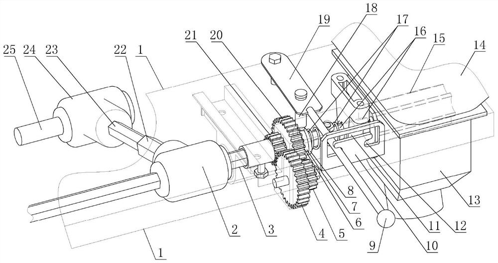
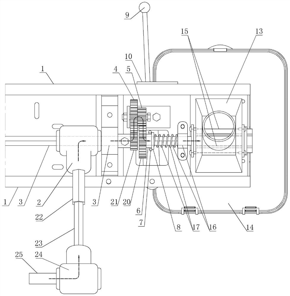
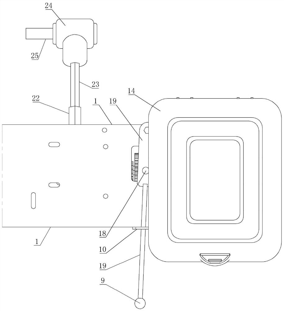
[0030] Mechanical fertilizer applicator deceleration clutch device, such as Figure 1 to Figure 5 As shown, it comprises a support 1 in the fertilizer applicator, a main reversing machine 2 and a fertilizer bucket 14 are housed on the support, and the main reversing machine is provided with a power output shaft 3 of the main reversing machine and a power input shaft 22 of the main reversing machine , the fertilizer outlet of the fertilizer hopper is equipped with a wheeled fertilization mechanism 13, a fertilizer wheel 15 that is connected in rotation is housed in the wheeled fertilizer mechanism, the first reduction gear 21 is fixed on the power output shaft of the main commutator, and the bracket Rotate the connected intermediate gear 4 and the fat wheel shaft 16, the intermediate gear is engaged with the first reduction gear, and the second reduction gear 5 is fixed on the intermediate gear; one end of the fat wheel shaft is fixedly connected with the fat wheel, and the clut...


PUM


Abstract

The invention discloses a speed reduction clutch device of a mechanical fertilizer applicator. A main reversing machine and a fertilizer hopper are installed on a support of the speed reduction clutch device, a fertilizer wheel is installed in a wheel type fertilizer application mechanism of a fertilizer outlet of the fertilizer hopper, an intermediate gear and a fertilizer wheel shaft which are connected in a rotating mode are installed on a support, a first speed reduction gear on a power output shaft of the main reversing machine is engaged with the intermediate gear, and a second speed reduction gear is fixedly installed on the intermediate gear. One end of the fertilizer wheel shaft is fixedly connected with the fertilizer wheel, the fertilizer wheel shaft is sleeved with a clutch gear which is fixed in the circumferential direction and connected in a sliding manner in the axial direction, and the clutch gear is located at one side dead point to be engaged with the second speed reduction gear and located at the other side dead point to be separated from the second speed reduction gear. The wheel diameters of the two speed reduction gears are smaller than those of the intermediate gear and the clutch gear. A displacement driving mechanism of the clutch gear is arranged on the support. The device can reduce the speed of the power of a power shaft on a agricultural machine carrier and then transmit the power to the fertilizer wheel shaft, the power is cut off or connected according to needs, the combination rushing impact force during power connection is small, and power transmission is reliable.

Description

technical field [0001] The invention relates to a power transmission device for a fertilizer applicator, in particular to a deceleration clutch device for a mechanical fertilizer applicator. Background technique [0002] The airborne fertilizer applicator is installed on the agricultural machinery carrier (such as a tractor) through its bracket, and the bracket is equipped with a fertilizer bucket. The fertilizer outlet of the fertilizer bucket is equipped with a wheeled fertilization mechanism, and the wheeled fertilizer mechanism is equipped with a fertilizer wheel connected by rotation. The fertilizer wheel rotates through the power provided by the agricultural machinery carrier. In the past, sprockets or gears were fixed on the wheel shaft of the agricultural machinery carrier, and the wheel shaft transmitted its torque to the fertilizer wheel shaft of the fertilizer wheel through a chain mechanism or a gear set. The installation and debugging of the structure is relativ...

Claims


Application Information

Patent Timeline
Patent Type & Authority Applications(China)
IPC IPC(8): F16H1/22F16H57/023F16D11/14F16D23/12F16D23/14A01C19/00
Inventor 董书银
Owner 董书银
Why Eureka
Try Eureka