
Machining device for sintered neodymium-iron-boron magnetic material

A processing device, NdFeB technology, applied in inductor/transformer/magnet manufacturing, electrical components, circuits, etc., can solve the problems of unnecessary time, long time consumption, low equipment work efficiency, etc. Efficiency, improve production capacity, improve the effect of work efficiency

Inactive Publication Date: 2021-04-16
GANZHOU FORTUNE ELECTRONICS
View PDF0 Cites 1 Cited by
  • Summary
  • Abstract
  • Description
  • Claims
  • Application Information

AI Technical Summary

Problems solved by technology

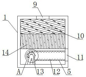
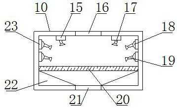
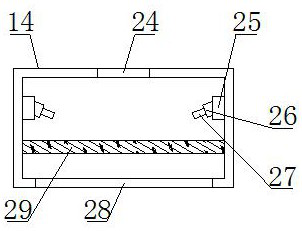
[0003] The technical problem to be solved in the present invention is to provide a processing device for sintered NdFeB magnetic materials, one of which is to have a material melter, a fixed melting accelerator box, a melting accelerator injector, a high-temperature production table, and a melting injector , to solve the problem that the existing processing device cannot quickly melt the material when it is in use, which makes the equipment work inefficient and consumes a long time; another purpose is to solve the problem that most of the existing processing device is in use. The equipment has only one shape and cannot shape the material in different shapes. It has the effect of enabling the device to shape the material in different shapes and improving the production capacity of the equipment. Another purpose is to have a cooling shaper , Cooler fixed table, high-efficiency cooler, and cold air injector are convenient to solve the problem that most of the existing processing devices cannot quickly cool the hot NdFeB magnets when they are in use, and it takes time to waste time after taking them out. The problem of cooling is conducive to rapid cooling of the hot junction NdFeB magnetic material, avoiding unnecessary time spent on cooling the parts when taking it out, and improving work efficiency

Method used


Image

  • Machining device for sintered neodymium-iron-boron magnetic material
  • Machining device for sintered neodymium-iron-boron magnetic material
  • Machining device for sintered neodymium-iron-boron magnetic material

Examples


Embodiment Construction

[0031] The following is attached Figure 1-6 The principles and features of the present invention are described, and the examples given are only used to explain the present invention, and are not used to limit the scope of the present invention. In the following paragraphs the invention is described more specifically by way of example with reference to the accompanying drawings. Advantages and features of the present invention will be apparent from the following description and claims. It should be noted that all the drawings are in a very simplified form and use imprecise scales, and are only used to facilitate and clearly assist the purpose of illustrating the embodiments of the present invention.

[0032] It should be noted that when a component is said to be "fixed" to another component, it can be directly on the other component or there can also be an intervening component. When a component is said to be "connected" to another component, it may be directly connected to ...


PUM


Abstract

The invention relates to a machining device for a sintered neodymium-iron-boron magnetic material, and relates to the technical field of neodymium-iron-boron machining. The machining device comprises a machining device body, a material melting device and a cooling shaper. A material feeder is fixedly installed at the top of the machining device body, a body supporting frame is fixedly installed at the bottom of the machining device body, a goods outlet pipeline is welded to the right side of the machining device body, and the top of the material melting device is fixedly installed at the top end of the inner wall of the machining device body. Through ingenious design and combination of the material melting device, a fixed melting promoting box, a melting promoting agent ejector, a high-temperature manufacturing table and a melting ejector, the problems that when an existing machining device is used, materials cannot be quickly melted, the working efficiency of equipment is low, and consumed time is long are conveniently solved, materials can be quickly melted during use of the device, the consumption of excessive unnecessary time is avoided, and the working efficiency of the equipment is improved.

Description

technical field [0001] The invention relates to the technical field of NdFeB processing, in particular to a processing device for sintered NdFeB magnetic materials. Background technique [0002] NdFeB permanent magnet material is a permanent magnet material based on the intermetallic compound ND2FE14B. The main components are rare earth, iron and boron. The sintered NdFeB permanent magnet material adopts the powder metallurgy process. Before production and processing, the sintered NdFeB permanent magnet material needs to be crushed to obtain fine powder. Generally, a jet mill is used for crushing, and the raw materials are added to the vacuum melting furnace according to the specified mass fraction, and the belt is thrown after high-temperature melting; The alloy flakes are first crushed in a hydrogenation furnace, and then made into fine powder in a jet mill; the fine powder is pressed under the protection of nitrogen to obtain a blank; the pressed blank is put into a vac...

Claims


Application Information

Patent Timeline
IPC IPC(8): H01F41/02
Inventor 庞再升喻玺王亮亮袁维仁刘滨
Owner GANZHOU FORTUNE ELECTRONICS
Learn More