
Vacuum packaging equipment with failure alarm function for optical lens

A technology of optical lenses and vacuum packaging, applied in the field of optical lenses, can solve the problems of unpreserved lenses, lens pollution, easy damage and rupture of packaging bags, etc., to achieve the effect of convenient transfer and avoid mirror surface pollution

Inactive Publication Date: 2021-04-20
宜昌华悦光电科技有限公司
View PDF15 Cites 1 Cited by
  • Summary
  • Abstract
  • Description
  • Claims
  • Application Information

AI Technical Summary

Problems solved by technology

[0003] In the present stage of lens production, it is usually necessary to vacuum-pack the finished lenses. Vacuum packaging can make the lenses in a state of high pressure reduction, which can prevent harmful microorganisms from multiplying and protect the lenses from pollution. In the prior art, generally through Vacuumize the packaging bag for vacuum packaging of optical lenses, but the lens in the vacuum packaging bag is hard and brittle, and the impact caused by a slight collision during transportation will be directly transmitted to the lens, which will easily cause damage to the lens, and the packaging bag is easily damaged Cracks make the vacuum packaging state of the lenses disappear, and it is difficult to find out in time. The lenses in the broken packaging bags cannot be well preserved, making the lenses polluted

Method used


Image

  • Vacuum packaging equipment with failure alarm function for optical lens
  • Vacuum packaging equipment with failure alarm function for optical lens
  • Vacuum packaging equipment with failure alarm function for optical lens

Examples


Embodiment Construction

[0029] The following will clearly and completely describe the technical solutions in the embodiments of the present invention with reference to the accompanying drawings in the embodiments of the present invention. Obviously, the described embodiments are only some, not all, embodiments of the present invention. Based on the embodiments of the present invention, all other embodiments obtained by persons of ordinary skill in the art without creative efforts fall within the protection scope of the present invention.

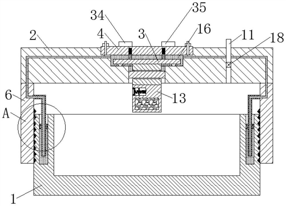
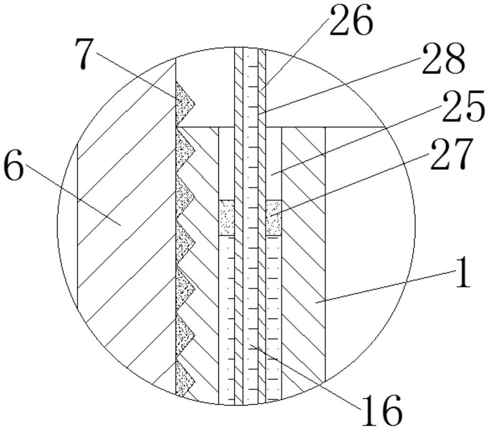
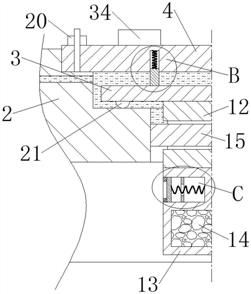
[0030] like Figure 1-7 As shown, a vacuum packaging equipment for optical lenses with a failure alarm function includes a box body 1, a cover plate 2, a disc 3 and a permanent disk 4; the box body 1 is a cylindrical cavity structure with an open top, and the box body The upper part of the outer wall of 1 is provided with an internal thread 5, and the lower surface of the cover plate 2 is fixedly connected with an annular connecting sleeve 6. The inner diameter of ...


PUM


Abstract

The invention discloses vacuum packaging equipment with a failure alarm function for an optical lens. The vacuum packaging equipment with the failure alarm function for the optical lens comprises a box body, a cover plate, a disc and a permanent magnet disc, wherein a mounting groove, a liquid storage groove and a through groove are formed in the cover plate; the disc is arranged in the liquid storage groove; the lower part of the disc is fixedly connected with a containing box through a connecting rod; a getter is contained in the containing box; a sealing ring is fixedly connected to the position, corresponding to the through groove, on the connecting rod; and magnetorheological fluid is contained in the liquid storage groove. Due to the arrangement of the permanent magnet disc, the magnetorheological fluid, the connecting rod and the sealing ring, a limiting block, the connecting rod and the sealing ring can form an integral liquid seal by utilizing the morphological transformation of the magnetorheological fluid in a zero magnetic field environment and a strong magnetic field environment, and the magnetorheological fluid cannot flow again when being used for conducting liquid seal on the through groove; a groove is formed in the containing box; a limiting ring and a piezoelectric plate are fixedly connected into the groove; a sliding plate is further connected into the groove through a telescopic spring; and a controller and an alarm are fixedly connected onto the permanent magnet disc.

Description

technical field [0001] The invention relates to the technical field of optical lenses, in particular to a vacuum packaging device for optical lenses with a failure alarm function. Background technique [0002] Optical lenses are mixed with high-purity oxides of silicon, boron, sodium, potassium, zinc, lead, magnesium, calcium, barium, etc. according to a specific formula, melted at high temperature in a platinum crucible, stirred evenly with ultrasonic waves, and removed air bubbles; Slowly cool down over time to avoid internal stress in the glass block. The cooled glass block must be measured by optical instruments to check whether the purity, transparency, uniformity, refractive index and dispersion rate meet the specifications. Qualified glass blocks are heated and forged to form Optical lens blanks. [0003] In the present stage of lens production, it is usually necessary to vacuum-pack the finished lenses. Vacuum packaging can make the lenses in a state of high pressur...

Claims


Application Information

Patent Timeline
Patent Type & Authority Applications(China)
IPC IPC(8): B65D25/02B65D81/20B65D53/02B65D53/06B65D79/02B65D85/38B65D81/26
Inventor 李家华
Owner 宜昌华悦光电科技有限公司
Learn More