Spot welding quality monitoring device and method based on dynamic machine vision

A machine vision and quality monitoring technology, applied in welding monitoring devices, welding power sources, welding equipment, etc., can solve problems such as the inability to guarantee 100% solder joint inspection, the inability to meet the needs of fast-paced production, and the poor timeliness of quality feedback. Rich and perfect welding process and low hardware cost

Pending Publication Date: 2021-04-23
NANCHANG UNIV
View PDF0 Cites 6 Cited by
  • Summary
  • Abstract
  • Description
  • Claims
  • Application Information

AI Technical Summary

Problems solved by technology

This type of quality inspection method is inefficient and has poor quality feedback timeliness. It cannot meet the fast-paced production needs and cannot guarantee 100% inspection of solder joints. Enterprises can only ensure quality by increasing the number of solder joints, which will inevitably increase costs. Reduced efficiency

Method used


Image

  • Spot welding quality monitoring device and method based on dynamic machine vision
  • Spot welding quality monitoring device and method based on dynamic machine vision
  • Spot welding quality monitoring device and method based on dynamic machine vision

Examples


Embodiment Construction

[0038] Below in conjunction with accompanying drawing and embodiment the present invention is further described:

[0039] see Figure 1-10 .

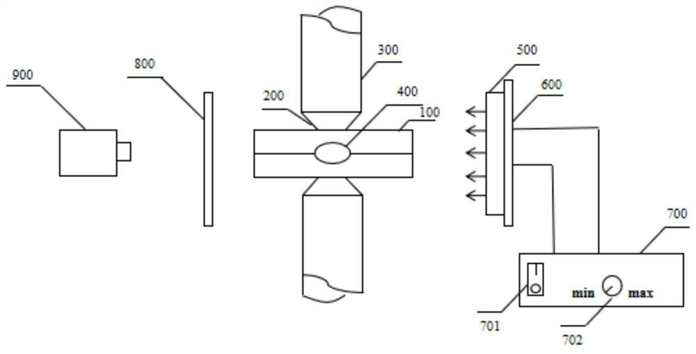
[0040] The invention discloses a spot welding quality monitoring device based on dynamic machine vision, such as figure 1 As shown, the workpiece 100 to be welded is placed between two identical spot welding electrodes 200, and the verticality between the electrode rod 300 and the workpiece 100 to be welded is 90°, which ensures the best spot welding angle and nugget position 400 is located at the center of the workpiece, so as to ensure that the pressure applied to the workpiece 100 to be welded is uniform during the spot welding process. The industrial square light source 500 is parallel to the right side of the workpiece 100 to be welded. The industrial square light source 500 can provide bright and uniform irradiation light and is fixed by the light source fixing frame 600 to keep it stable. The light source trigger simulator 700...


PUM


Abstract

The invention relates to the technical field of resistance spot welding application, in particular to a spot welding quality monitoring device and method based on dynamic machine vision. The device comprises a welded workpiece, spot welding electrodes, an electrode rod, an industrial square power supply and a dynamic machine vision monitoring system, wherein the spot welding electrodes are formed at an end of the electrode rod, and the welded workpiece is arranged between the two spot welding electrodes; and the industrial square power supply is arranged on the outer side of one end of the welded workpiece, and the dynamic machine vision monitoring system is arranged on the outer side of the other end of the welded workpiece. The method comprises the steps of acquiring data associated with the resistance spot welding process, detecting parameters associated with splashing from the acquired data, analyzing the detected parameters, shooting the splashing condition during spot welding by using a high-speed industrial camera, determining the number of generated splashes, the splashing morphology and the splashing direction by adopting image processing, and establishing a database so as to monitor splashing generation events in the resistance spot welding process.

Description

technical field [0001] The invention relates to the technical field of resistance spot welding applications, in particular to a spot welding quality monitoring device and method based on dynamic machine vision. Background technique [0002] Resistance spot welding is to press the workpiece to be welded between the two electrodes, and pass the current, and use the resistance heat generated by the current flowing through the contact surface of the workpiece and the adjacent area to heat it to a molten state to form a metal bond. Way. Resistance spot welding has been widely used in automobiles, rail transit, aerospace, low-voltage electrical appliances, home appliances, batteries and other fields due to its advantages of low cost, high production efficiency and easy automation. Especially in the automotive industry, more than 90% of body assembly work is done by resistance spot welding. [0003] However, spatter is unavoidable in the resistance spot welding process. The root...

Claims


Application Information

Patent Timeline
Patent Type & Authority Applications(China)
IPC IPC(8): B23K11/25B23K11/11B23K11/36
CPCB23K11/11B23K11/25B23K11/36
Inventor 朱政强吴蔺峰王晓东冯杉杉
Owner NANCHANG UNIV
Why Eureka
Try Eureka