Binocular camera system and binocular camera space calibration method

A binocular camera and camera technology, applied in computer parts, character and pattern recognition, image data processing and other directions, can solve the problems of loss of spatial depth information, reduce imaging quality, etc., and achieve the effect of improving imaging quality and improving accuracy.

Active Publication Date: 2021-04-23
XIDIAN UNIV
View PDF5 Cites 3 Cited by
  • Summary
  • Abstract
  • Description
  • Claims
  • Application Information

AI Technical Summary

Problems solved by technology

[0005] The application publication number is CN108038888A, titled "Hybrid Camera System and Its Spatial Calibration Method and Device", which discloses a hybrid camera system and its spatial calibration method. This camera and its spatial calibration method use an event camera, a common CMOS camera and a beam splitter A binocular camera system is formed to achieve spatial calibration by minimizing the spatial projection error. Its shortcoming is that the spatial position between the event camera and the ordinary CMOS camera is roughly calibrated by using a spectroscopic sheet, resulting in that each of the two cameras can only receive insufficient 50% of the light reduces the image quality; the use of a beam splitter results in no parallax between the two cameras and the loss of spatial depth information

Method used


Image

  • Binocular camera system and binocular camera space calibration method
  • Binocular camera system and binocular camera space calibration method

Examples


Embodiment 1

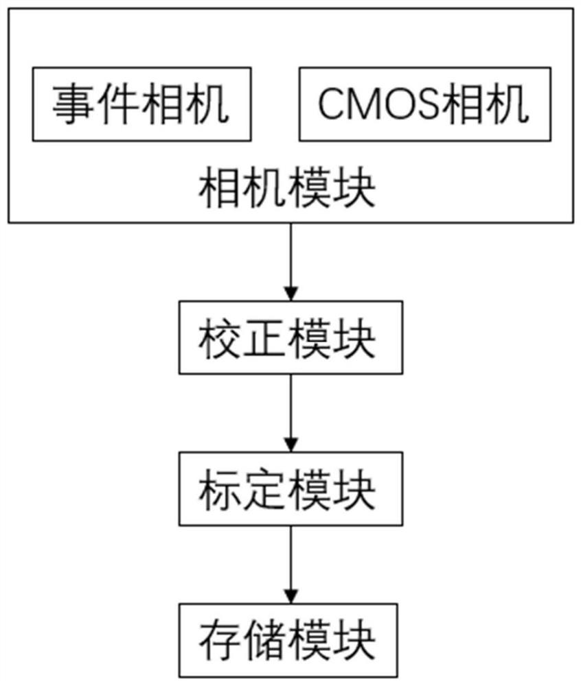
[0029] Due to the limitation of the imaging principle of the existing common CMOS camera, common CMOS cameras have smear phenomenon when shooting high-speed moving targets, which will cause blurred images, and it is difficult to effectively use the image data captured by them. The event camera is a camera with a different imaging principle from the ordinary CMOS camera. The event camera simulates the imaging characteristics of the biological retina. It only images moving targets, so the data volume of the event camera is smaller, and it can shoot high-speed moving targets. Combining a CMOS camera and an event camera to form a binocular camera system can effectively use the advantages of the two cameras to obtain data with the advantages of high frame rate, high dynamic range, and high spatial resolution.

[0030] The present invention is a binocular camera system, see figure 1 , the binocular camera system of the present invention is sequentially cascaded with a camera module,...

Embodiment 2

[0041] The overall composition of a binocular camera system is the same as in Embodiment 1. The camera matrix and distortion matrix of the pre-calibrated event camera stored in the correction module of the present invention are obtained by Zhang Zhengyou's calibration method, and the camera of the pre-calibrated CMOS camera stored in the correction module The matrix and distortion matrix are obtained by Zhang Zhengyou’s calibration method; the rotation matrix and translation matrix between the pre-calibrated event camera and the CMOS camera stored in the correction module are obtained by Bouguet’s epipolar correction method. In this embodiment, when calibrating the event camera and the common CMOS camera, the calibration board used is a checkerboard calibration board. When calibrating the event camera in this camera, a full-scale grayscale image is acquired through the Celex-V camera.

[0042] The invention performs distortion correction on each camera in the binocular camera ...

Embodiment 3

[0044] Due to the parallax between the two cameras in the binocular camera system in the present invention, the coordinates of the same target on the image planes of the two cameras are related to the relative positions of the target and the binocular camera system. When the relative position of the binocular camera system changes, the coordinates of the target on the respective image planes of the two cameras in the binocular camera system will also change. The camera system is calibrated in real time. The spatial calibration method of the present invention utilizes the binocular camera system of the present invention to capture data in real time, and then corrects and calibrates these data in real time.

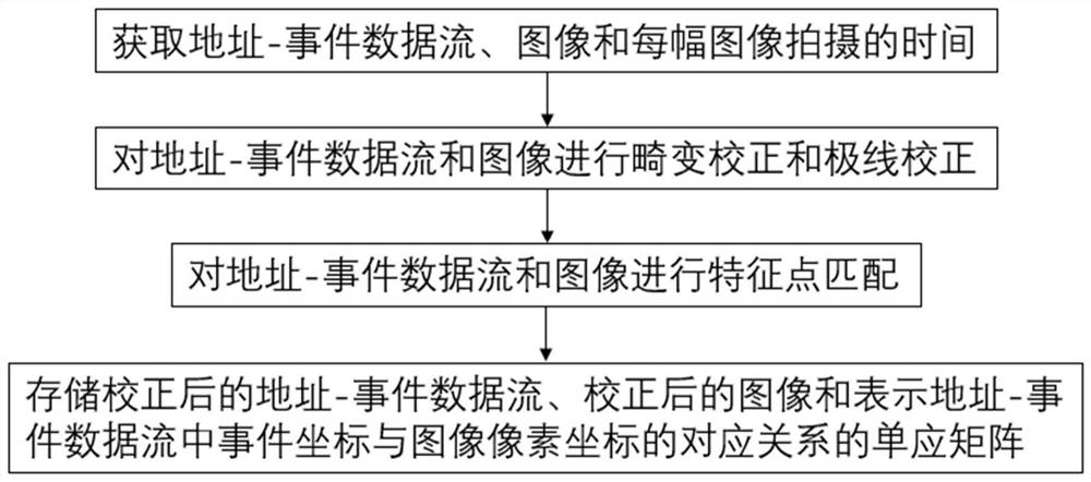
[0045] The present invention is also a binocular camera space calibration method, which is implemented on the above binocular camera system, see figure 2 , including the following steps:

[0046] (1) The camera module obtains the address-event data stream, images and the...


PUM


Abstract

The invention provides a binocular camera system and a binocular camera space calibration method, and solves the problems of poor imaging quality and no depth information in the prior art. The binocular camera system is sequentially cascaded with a camera module, a correction module, a calibration module and a storage module; the camera module comprises an event camera and a common CMOS camera which are connected in parallel. The space calibration method comprises the steps that a camera module acquires an address-event data stream, an image and shooting time; the correction module performs distortion and epipolar correction on the data stream and the image; the calibration module calibrates the spatial positions of the corrected data stream and the image; and the storage module stores the corrected data streams, images and corresponding relations thereof in a persistent memory in a homography matrix set. A spectroscope is not needed, and poor imaging caused by the spectroscope is avoided. The system has parallax, and the spatial depth information can be recovered through the parallax. The system is used in the fields of high-frame-rate and high-resolution data reconstruction, high-speed moving target identification and tracking and the like.

Description

technical field [0001] The invention belongs to the technical field of computer vision, and relates to the structure and spatial calibration of a binocular camera, in particular to a binocular camera system and a binocular camera space calibration method, which are used to reconstruct image data with high temporal resolution and high spatial resolution. Improve the accuracy of high-speed moving target recognition and tracking, and can also be used for spatial calibration of binocular camera systems including event cameras and ordinary CMOS cameras. Background technique [0002] The binocular camera system can obtain the distance between the object and the camera through the parallax of the two cameras, and is widely used in the fields of robotics and SLAM. However, there are many defects in the binocular camera system using a common CMOS camera. When the relative motion between the binocular camera system and the target is too fast, serious image blurring will occur, making ...

Claims


Application Information

Patent Timeline
Patent Type & Authority Applications(China)
IPC IPC(8): G06T7/80G06T5/00G06T7/33G06K9/46
CPCG06T7/80G06T5/006G06T7/33G06V10/462
Inventor 吴金建李汉标石光明
Owner XIDIAN UNIV
Why Eureka
Try Eureka