Bandpass frequency selective surface structure based on antenna, filter and antenna

A technology of frequency selective surface and frequency selection, applied in the direction of antennas, electrical components, etc., can solve the problems of low profile, thick structural profile, poor out-of-band selectivity, etc., and achieve the effect of low profile, good angular stability, and easy processing

Active Publication Date: 2021-04-23
SHENZHEN UNIV
View PDF18 Cites 0 Cited by
  • Summary
  • Abstract
  • Description
  • Claims
  • Application Information

AI Technical Summary

Problems solved by technology

[0007] The technical problem to be solved by the present invention is to design a band-pass frequency selective surface structure that is easy to process, has a

Method used


Image

  • Bandpass frequency selective surface structure based on antenna, filter and antenna
  • Bandpass frequency selective surface structure based on antenna, filter and antenna
  • Bandpass frequency selective surface structure based on antenna, filter and antenna

Examples


Embodiment 1

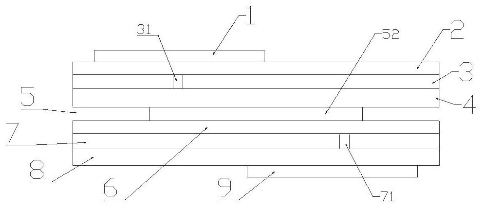
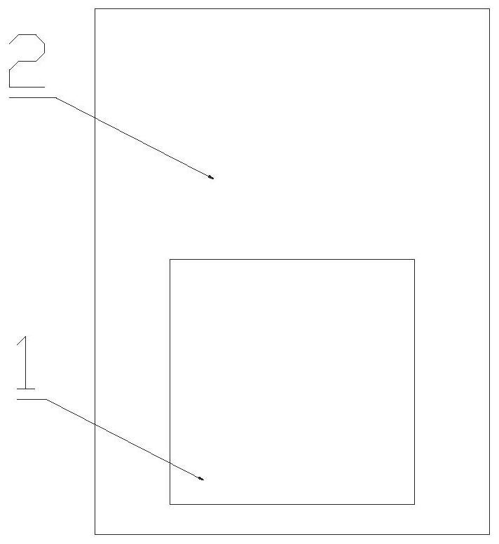
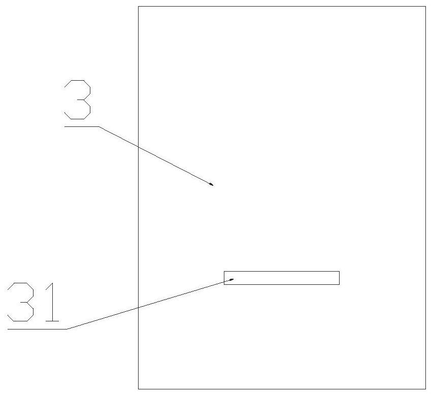
[0033] see Figure 1 to Figure 6 , a band-pass frequency selective surface structure based on antenna-filter-antenna, including a frequency selective unit, the frequency selective unit is composed of a first radiation patch 1, a first dielectric plate 2, and a first metal floor 3 stacked in sequence , a second dielectric plate 4, a resonant layer 5, a third dielectric plate 6, a second metal floor 7, a fourth dielectric plate 8 and a second radiation patch 9; the first metal floor 3 is provided with a first gap 31. The projections of the first slit 31 all fall on the first radiation patch 1, that is, the projections of the first slit 31 on the plane where the first radiation patch 1 is located all fall on the first radiation patch 1. On the radiation patch 1; the second metal floor 7 is provided with a second gap 71, and the projections of the second gap 71 all fall on the second radiation patch 9, that is, the second gap 71 falls on the The projections of the plane where the...

Embodiment 2

[0036] On the basis of the above structure, the length directions of the first slot 31 and the second slot 71 are parallel to the length direction of the first microstrip 51 . Under the irradiation of a plane wave whose polarization direction is perpendicular to the first slot 31 / second slot 71, when the incident angle increases from 0° to 40°, it still has a very stable frequency response and good angular stability.

Embodiment 3

[0038] On the basis of the above structure, the first radiating patch 1 and the second radiating patch 9 are both rectangular patches, and the projection of the first radiating patch 1 falling on the resonance layer 5 and the The projection of the second radiation patch 9 falling on the resonant layer 5 is separated on both sides of the first microstrip 51, further improving the stability of the quasi-elliptic filter response based on the antenna-filter-antenna bandpass frequency selective surface structure , selectivity and angular stability.


PUM

PropertyMeasurementUnit
Side lengthaaaaaaaaaa
Thicknessaaaaaaaaaa
Thicknessaaaaaaaaaa

Abstract

The invention provides a bandpass frequency selective surface structure based on an antenna, a filter and an antenna. The structure comprises a frequency selection unit which consists of a first radiation patch, a first dielectric plate, a first metal floor, a second dielectric plate, a resonance layer, a third dielectric plate, a second metal floor, a fourth dielectric plate and a second radiation patch; the projections of first slots formed in the first metal floor fall on the first radiation patch; the projections of second slots formed in the second metal floor fall on the second radiation patch; the resonance layer is composed of a first microstrip and a second microstrip which are orthogonal to each other; the projections of the first slots on the resonance layer and the projections of the second slots on the resonance layer are located at two sides of the first microstrip; the length direction of the first slots and the length direction of the second slots are consistent with the length direction of the first microstrip. The structure generates four transmission extreme points and two transmission zero points in total, and has stable quasi-elliptic filter response and high selectivity, good angle stability and low profile.

Description

technical field [0001] The invention relates to the technical field of frequency surface selection, in particular to an antenna-filter-antenna-based bandpass frequency selection surface structure. Background technique [0002] Frequency Selective Surface (FSS) is a two-dimensional periodic surface structure that can reflect or transmit electromagnetic waves. There are two types of traditional frequency selective surfaces, namely frequency selective surfaces with slots and patch periodic units. The patch type has the same metal units periodically on the surface of the medium. The other is the slit type, which is a structure in which slits are periodically etched on the metal plate. When the FSS is in a resonant state, the incident electromagnetic wave undergoes total reflection or transmission, which can be used as a spatial filter and can be widely used in anti-electromagnetic interference, electromagnetic compatibility, anti-electric radiation, antenna decoupling, etc. A...

Claims


Application Information

Patent Timeline
IPC IPC(8): H01Q15/00
CPCH01Q15/0026
Inventor 李银杜志敏王世伟刘柏杨陈国文胡熊敏
Owner SHENZHEN UNIV
Why Eureka
Try Eureka