
Electric spindle water cooling structure

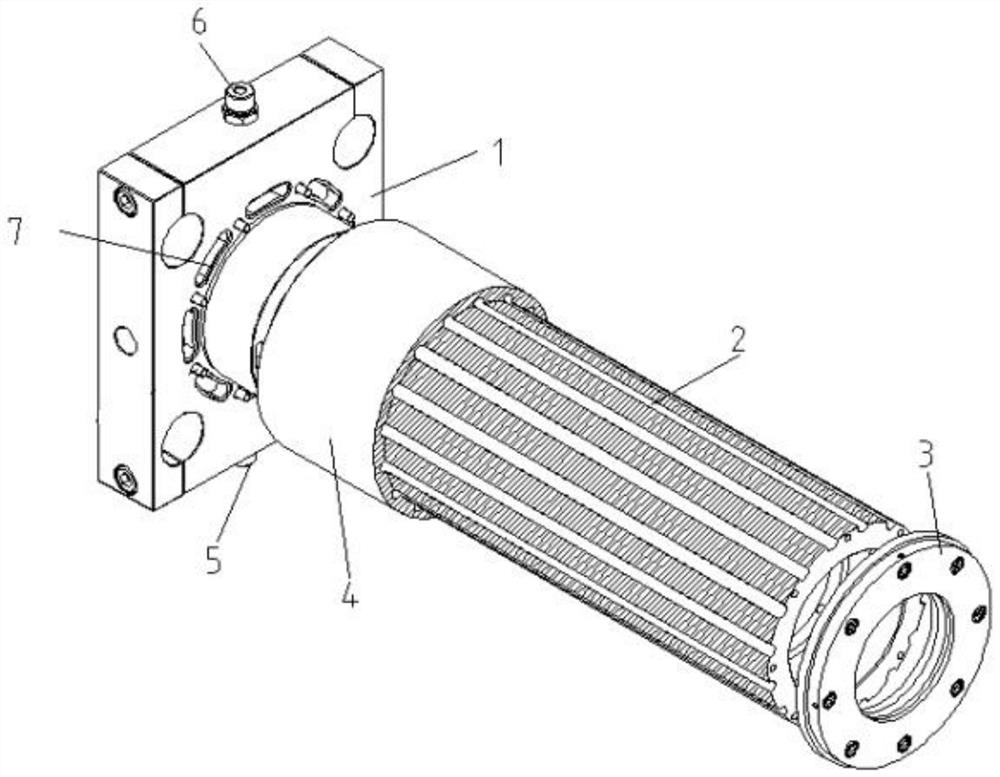
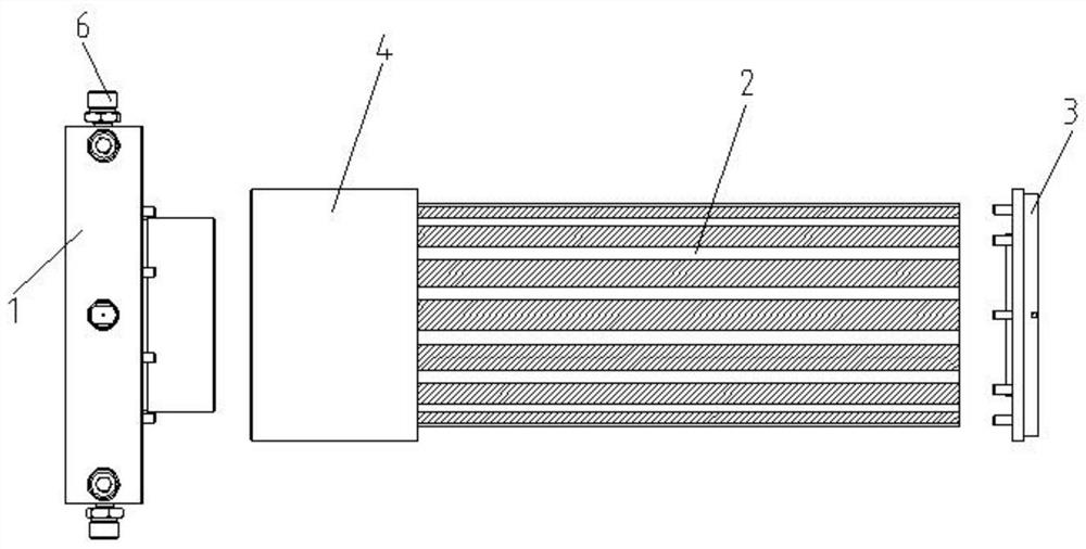
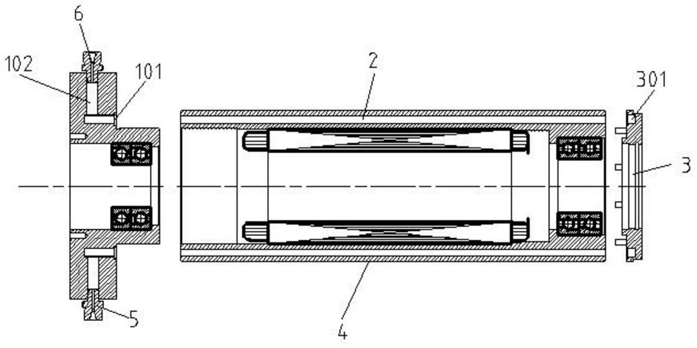
A technology of water cooling and electric spindle, which is applied in the direction of large fixed members, metal processing machinery parts, maintenance and safety accessories, etc. It can solve the problems of poor cooling effect, high processing cost, large volume and insufficient simplicity, etc., to reduce manufacturing procedures and Low cost, guaranteed mechanical strength, and high rigidity

Pending Publication Date: 2021-04-27
台州市神鹰机床有限公司
View PDF0 Cites 1 Cited by
  • Summary
  • Abstract
  • Description
  • Claims
  • Application Information

AI Technical Summary

Problems solved by technology

Thus, the transmission performance, high-speed response and stability of the machine tool spindle are improved. The main structure of the machine tool electric spindle includes: the spindle box installed on the machine tool, and the high-speed spindle is installed on the spindle box through the front and rear end covers and front and rear bearings. The stator is nested in the main shaft housing, and the rotor matched with the stator is fixedly installed on the main shaft. However, when the electric spindle of the machine tool in the prior art is processed, because the front and rear bearings bear large radial force and axial force, the front and rear The bearing will emit a lot of heat when it is working, and the stator and rotor will generate a lot of heat during work, which will affect the service life. At this stage, when designing the electric spindle, water cooling is added to the electric spindle to cool down the electric spindle. In order to ensure the stability of the electric spindle, it is common to set up a spiral groove 8 on the surface of the spindle sleeve, and then set a seal at both ends of the shell, in which the spiral groove is as follows Image 6 As shown, but the common structure reduces the mechanical rigidity of the electric spindle as a whole, and the volume is large and not simple enough, the processing cost is high, and the cooling effect is poor.

Method used


Image

  • Electric spindle water cooling structure
  • Electric spindle water cooling structure
  • Electric spindle water cooling structure

Examples


Embodiment Construction

[0025] The following will clearly and completely describe the technical solutions in the embodiments of the present invention with reference to the accompanying drawings in the embodiments of the present invention. Obviously, the described embodiments are only some, not all, embodiments of the present invention. Based on the embodiments of the present invention, all other embodiments obtained by persons of ordinary skill in the art without creative efforts fall within the protection scope of the present invention.

[0026] In describing the present invention, it is to be understood that the terms "opening", "upper", "lower", "thickness", "top", "middle", "length", "inner", "surrounding" etc. Indicating orientation or positional relationship is only for the convenience of describing the present invention and simplifying the description, and does not indicate or imply that the components or elements referred to must have a specific orientation, be constructed and operated in a sp...


PUM


Abstract

The invention discloses an electric spindle water cooling structure, and belongs to the technical field of machine tool electric spindles. The electric spindle water cooling structure comprises a spindle sleeve, a gland type rear bearing seat and a front bearing end cover, the gland type rear bearing seat and the front bearing end cover are arranged at the two ends of the spindle sleeve in a matched mode, the spindle sleeve is provided with more than one even number of heat exchange channels penetrating through the two ends of the spindle sleeve, the gland type rear bearing seat is provided with a circle of first conversion opening, and the front bearing end cover is provided with a circle of second conversion opening. Two flow channels are formed in the gland type rear bearing seat, a first conversion opening, a second conversion opening and the two heat exchange channels form a circuitous flow channel, and the flow channels and the circuitous flow channels form one or two cooling liquid channels. The sleeve of the electric spindle is machined in the mode of forming the hole channel, and the mechanical strength of the spindle sleeve can be guaranteed under the condition that the electric spindle can be effectively cooled.

Description

technical field [0001] The invention belongs to the technical field of electric spindles for machine tools, and in particular relates to a water cooling structure for electric spindles. Background technique [0002] At present, the machine tool electric spindle is a product that integrates the stator and rotor with the machine tool spindle. It directly connects the rotor of the stator and rotor to the main shaft, thereby eliminating the transmission mechanism, and the power can be directly generated by the stator and rotor and transmitted to the main shaft. Thus, the transmission performance, high-speed response and stability of the machine tool spindle are improved. The main structure of the machine tool electric spindle includes: the spindle box installed on the machine tool, and the high-speed spindle is installed on the spindle box through the front and rear end covers and front and rear bearings. The stator is nested in the main shaft housing, and the rotor matched with...

Claims


Application Information

Patent Timeline
IPC IPC(8): B23B19/02B23Q11/12
CPCB23Q1/70B23Q11/127
Inventor 张兆富
Owner 台州市神鹰机床有限公司
Learn More