Alloy flange machining forming assembly line

A technology of processing and forming, alloy method, applied in the direction of metal processing, metal processing equipment, metal processing machinery parts, etc., can solve the problems of easy deformation, demand and low work efficiency of flange drills

Inactive Publication Date: 2021-04-30
南京旺财办公用品有限公司
View PDF0 Cites 5 Cited by
  • Summary
  • Abstract
  • Description
  • Claims
  • Application Information

AI Technical Summary

Problems solved by technology

[0003] 1. In the process of drilling holes in the traditional flange, a single drilling method with a non-adjustable number of drill bits is adopted. When the number of drill bits needs to be adjusted and changed, the drill bits are repeatedly disassembled, thereby reducing the service life of the drill bits. Such a drill The hole method leads to cumbersome workflow and requires manual operation, resulting in low work efficiency;
[0004] 2. When conveying the flange that needs to be processed, the conveyor belt is usually used for conveying. During the process of drilling the flange with the drill bit, the drill bit exerts a certain pressure on the flange, and the flange moves downward on the conveyor belt. When pressing, due to the elastic movement of the conveyor belt, the depth of the drill bit to the flange cannot meet the requirements;
[0005] 3. When positioning and clamping the flange that needs to be processed, manual positioning and clamping of the chuck is usually used. Due to the lack of strength of the operator, the flange moves when the drill bit drills the flange. As a result, the drill bit is prone to deformation in the hole drilled by the flange

Method used


Image

  • Alloy flange machining forming assembly line
  • Alloy flange machining forming assembly line
  • Alloy flange machining forming assembly line

Examples


Embodiment Construction

[0032] The embodiments of the present invention will be described in detail below with reference to the accompanying drawings, but the present invention can be implemented in many different ways as defined and covered by the claims.

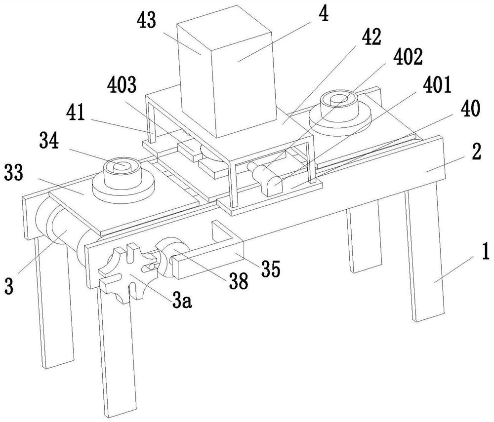
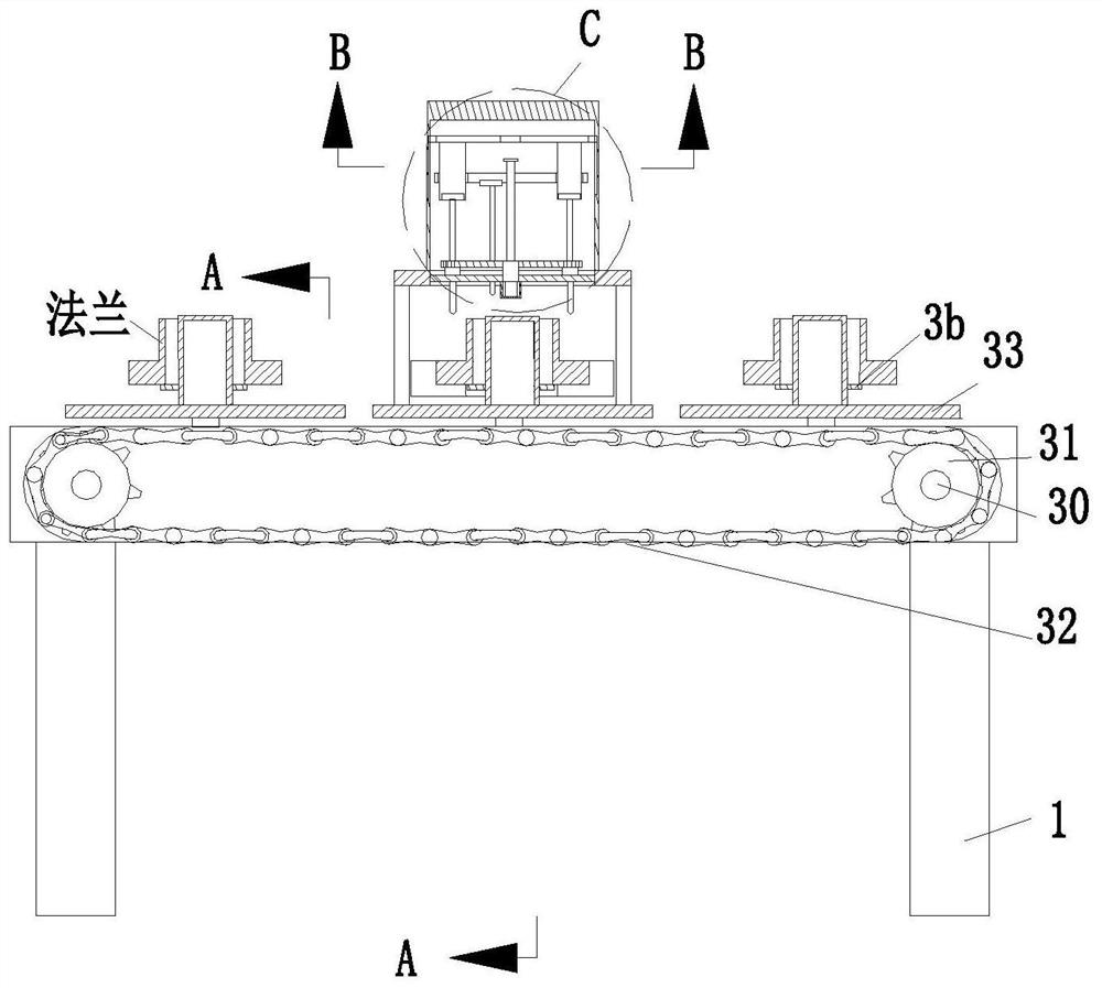
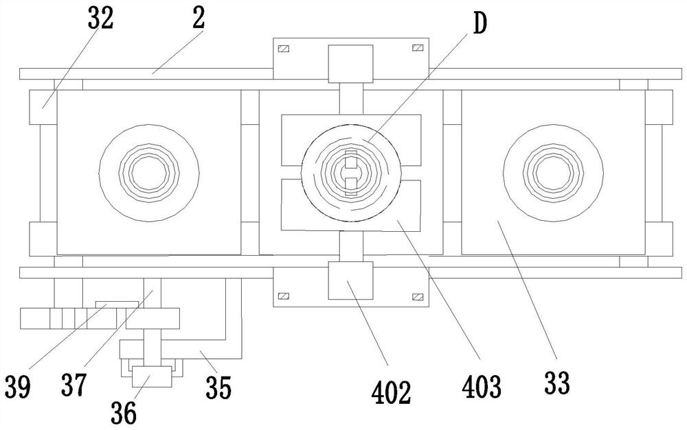
[0033] like Figure 1 to Figure 10 As shown, an alloy flange processing and forming line includes a support frame 1, a rectangular plate 2, a transmission mechanism 3 and a drilling mechanism 4. The four support frames 1 are arranged in a matrix, and the left and right two support frames A No. 1 rectangular plate 2 is installed on the upper end of the plate 1. A transmission mechanism 3 is arranged on the opposite surface of the No. 1 rectangular plate 2. A drilling mechanism 4 is arranged above the transmission mechanism 3.

[0034] Described transmission mechanism 3 comprises rotating shaft 30, sprocket wheel 31, chain 32, square plate 33, hollow cylinder 34, support ring 3b, L-shaped plate 35, motor No. 1 36, round shaft 37, semidisc 38, shake...


PUM


Abstract

The invention relates to an alloy flange machining forming assembly line. The alloy flange machining forming assembly line comprises supporting frames, first rectangular plates, a conveying mechanism and a drilling mechanism, wherein the four supporting frames are arranged in a matrix manner; the first rectangular plates are arranged on the upper end faces of the left supporting frame and the right supporting frame; the conveying mechanism is arranged on the opposite faces of the first rectangular plates; the drilling mechanism is arranged above the conveying mechanism; the conveying mechanism adopted in the alloy flange machining forming assembly line conveys a flange through a chain, then the outer portion of the flange is clamped through a clamping plate, the interior of the flange is clamped through a second pushing and extruding rod, then the drilling mechanism is adopted for conducting adjustment according to the needed drill bit number, the flange is drilled after adjustment, repeated dismounting of operators on drill bits is avoided, the service life of the drill bits is prolonged, and meanwhile the work efficiency is improved; and a square plate on the upper end face of the chain supports the flange, the situation that when the drill bits are used for drilling the flange, the flange moves downwards, and consequently the drilling depth is not enough is avoided, and accordingly the machining efficiency is improved.

Description

technical field [0001] The invention relates to the technical field of flange processing, in particular to an alloy flange processing and forming line. Background technique [0002] Flanges are also called flange flanges or flanges. They are parts that are connected to each other between shafts. They are used for connection between pipe ends. They are also useful for flanges on equipment inlets and outlets. The connection between the reducer, such as the reducer flange, flange connection or flange joint, refers to the detachable connection of flanges, gaskets and bolts as a combined sealing structure. Pipeline flange refers to the pipeline installation The flange used in the middle pipe is used on the equipment to refer to the inlet and outlet flanges of the equipment. There are holes on the flange, and the bolts make the two flanges tightly connected. The gasket is used to seal the flanges. Connection) flanges, welding flanges and clip flanges, but the following problems w...

Claims


Application Information

Patent Timeline
Patent Type & Authority Applications(China)
IPC IPC(8): B23B41/00B23B47/00B23Q3/154B23Q7/03B23Q15/14
CPCB23B41/00B23B47/00B23Q3/1543B23Q7/03B23Q15/14
Inventor 周嘉旺
Owner 南京旺财办公用品有限公司
Why Eureka
Try Eureka