
Dual-motor driving system assembly and vehicle

A dual-motor drive and motor-driven technology, which is applied to vehicle components, transportation and packaging, and control devices, can solve the problems of enlarging the envelope of the powertrain, increasing the axial width of the powertrain, and increasing the cost. Improve the ability to get out of trouble, improve the overall benefit, and improve the effect of parking safety and reliability

Pending Publication Date: 2021-04-30
JING JIN ELECTRIC TECH CO LTD
View PDF0 Cites 2 Cited by
  • Summary
  • Abstract
  • Description
  • Claims
  • Application Information

AI Technical Summary

Problems solved by technology

[0003] Due to some application scenarios of the dual-motor drive system, a large input-output center distance is required to meet the installation and layout of the drive axle space. For example, by increasing the arrangement of some accessories in the large center-to-center distance space, the diversity of products can be increased. ; If a two-stage gear transmission is used, if a larger center distance is set, the diameter of the driven gear needs to be increased, resulting in an increase in the envelope of the powertrain, which cannot meet the installation and layout requirements; if a three-stage gear transmission is used, It will increase the number of gears, increase the axial width of the powertrain, and increase the cost.

Method used


Image

  • Dual-motor driving system assembly and vehicle
  • Dual-motor driving system assembly and vehicle
  • Dual-motor driving system assembly and vehicle

Examples


Embodiment 1

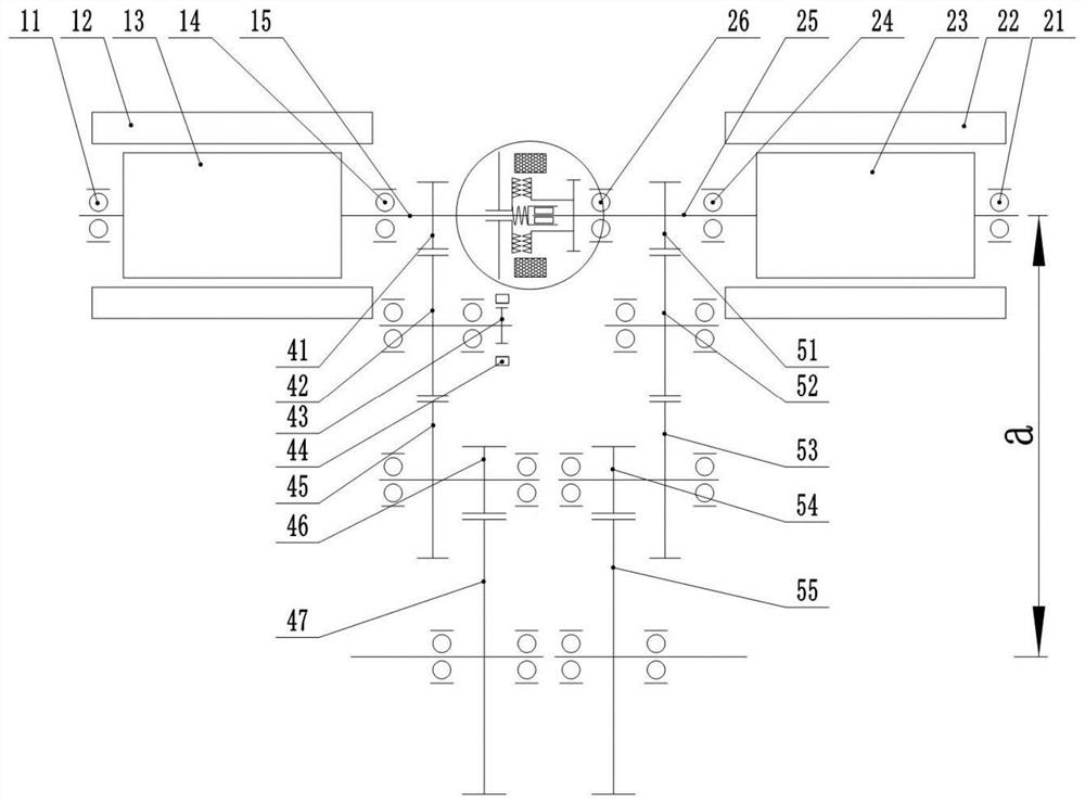
[0051] For the dual-motor drive system assembly in Embodiment 1, see figure 1 and the aforementioned description. It should be pointed out that, figure 1 The differential lock mechanism can be realized by locking the output shaft 15 of the first motor and the output shaft 25 of the second motor through an electromagnetic clutch; specifically, the following scheme can be used: the movable chain plate assembly 31 and the output shaft 15 of the first motor pass through The spline sliding connection, the fixed gear plate assembly 35 and the output shaft 25 of the second motor are fixedly connected by splines and other connection methods; the parking gear is integrated on the fixed gear plate, which can effectively reduce the number of parts and the assembly shaft The fixed electromagnetic coil 33 is energized to generate electromagnetic force, so that the movable toothed plate assembly 31 moves in the direction of the fixed toothed plate assembly 35, and the end face teeth on the...

Embodiment 2

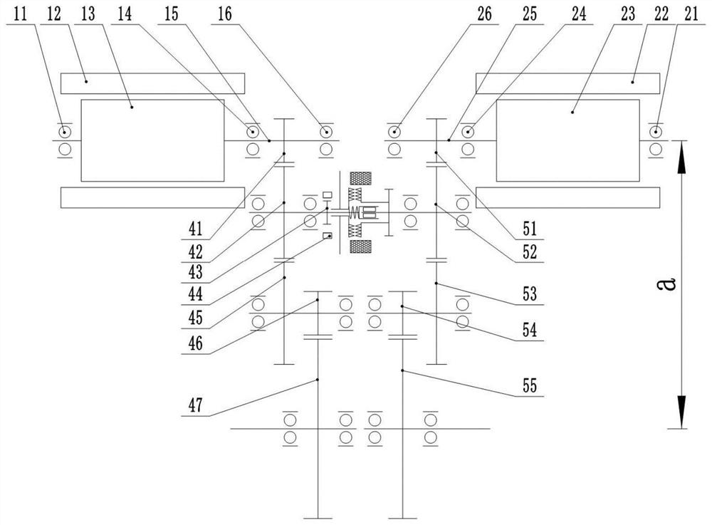
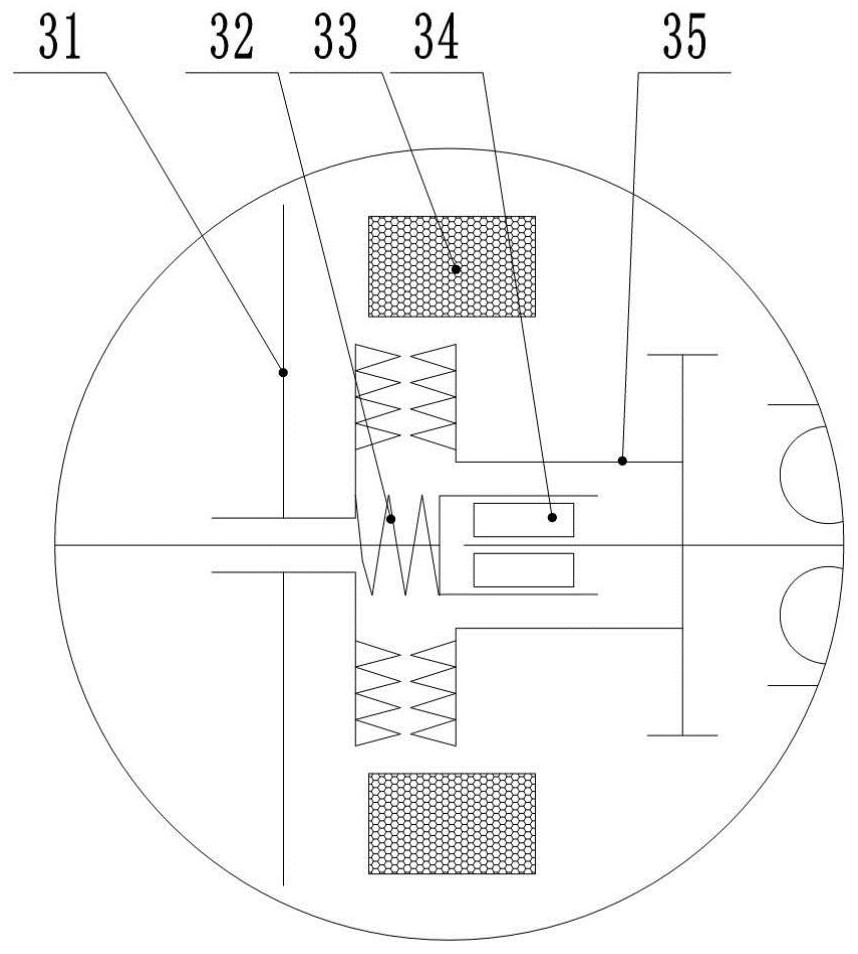
[0054] For the dual-motor drive system assembly in Embodiment 2, see figure 2 and the aforementioned description. It should be pointed out that the differential lock mechanism can be realized by the idler gear I42 and the idler gear II52; specifically, the following scheme can be used: the movable chainring assembly 31 and the idler gear I42 are slidably connected by a spline, and the fixed chainring assembly 35 and the idler gear are slidably connected. II52 is fixedly connected by splines and other connection methods; the parking gear is integrated on the fixed gear plate, which can effectively reduce the number of parts and the axial size of the assembly; the fixed electromagnetic coil 33 is energized to generate electromagnetic force, which makes the movable tooth The disc assembly 31 moves towards the fixed toothed disc assembly 35, and achieves mutual meshing and locking through the end face teeth on the toothed disc, reaching the function of locking the idler gear I an...


PUM


Abstract

The invention discloses a dual-motor driving system assembly and a vehicle. The dual-motor driving system assembly comprises a first motor and a second motor which are coaxially arranged, a first gear transmission, a second gear transmission and a plurality of idle wheel pairs, the first gear transmission is driven by the first motor, the second gear transmission is driven by the second motor, and the idler wheel pairs are arranged in the first gear transmission and the second gear transmission respectively and used for increasing the distance between an output shaft of the first motor and a tail end shaft of the first gear transmission. According to the scheme, due to the fact that the idle wheels are additionally arranged, the center distance between the input shaft and the output shaft in the assembly can be adjusted more flexibly by adjusting the size of the idle wheels, large-center-distance design is achieved, structural space brought by the large center distance is fully utilized for installing other components, and adjustment can be conducted according to space arrangement requirements and performance requirements of different clients.

Description

technical field [0001] The invention belongs to the technical field of power drive design, and particularly relates to a dual-motor drive system assembly and a vehicle. Background technique [0002] At present, the drive systems of pure electric vehicles mainly include single-motor centralized drive and multi-motor distributed drive. At present, some pure electric vehicles on the market mostly adopt a centralized drive scheme. The driving force of the motor is connected to the differential through gears, shafts, etc., and is roughly evenly distributed to the left and right half shafts. It is impossible to independently control a single wheel. Compared with single-motor centralized drive electric vehicles, the advantages of using dual-motor distributed independent wheel drive are: compact structure, convenient layout, and strong vehicle driving flexibility. The design of the dual-motor independent drive system needs to consider the space layout and the force of each shaft sy...

Claims


Application Information

Patent Timeline
Patent Type & Authority Applications(China)
IPC IPC(8): B60K17/04B60K17/16
CPCB60K17/04B60K17/16B60K7/0007B60K2007/0061B60K17/043B60K1/02F16H57/0441B60K25/06F16H37/0806F16H48/24F16H48/34F16H57/025F16H57/037F16H63/3425F16H2057/02026F16H2057/02034F16H2057/02052
Inventor 李建文王斐余平
Owner JING JIN ELECTRIC TECH CO LTD
Learn More