Soffit-type ultra-high performance concrete precast shield tunnel segment structure and design method

An ultra-high performance, tunnel segment technology, used in tunnels, earth-moving drilling, tunnel lining, etc., can solve the problems of stress relaxation bolt joints between annular joints, concrete damage, poor crack resistance and water leakage, etc. The effect of reducing the amount of concrete used, improving the bearing capacity and alleviating serious water leakage

Active Publication Date: 2021-06-18
HUNAN UNIV
View PDF5 Cites 0 Cited by
  • Summary
  • Abstract
  • Description
  • Claims
  • Application Information

AI Technical Summary

Problems solved by technology

[0005] The purpose of the present invention is to provide a soffit type ultra-high performance concrete prefabricated shield tunnel segment structure to solve the problems of poor crack resistance, serious water leakage, stress relaxation between annular joints and local concrete failure at bolt joints during the operation of the segment structure. Three major technical issues

Method used


Image

  • Soffit-type ultra-high performance concrete precast shield tunnel segment structure and design method
  • Soffit-type ultra-high performance concrete precast shield tunnel segment structure and design method
  • Soffit-type ultra-high performance concrete precast shield tunnel segment structure and design method

Examples


Embodiment 1

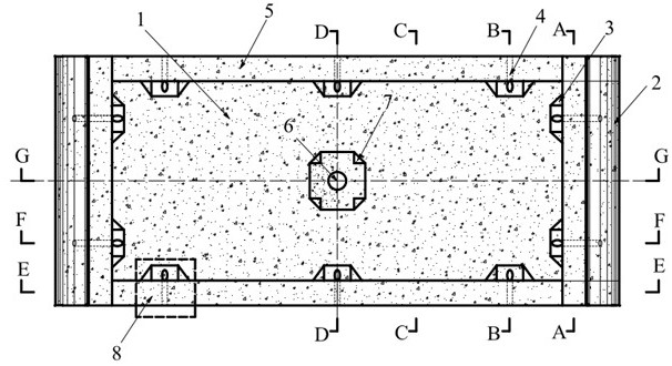
[0154] Such as Figure 1-11 As shown, a soffit type ultra-high performance concrete prefabricated shield tunnel segment, including:

[0155] Soffit 1, located in the soffit area of ​​the main body of the ultra-high performance concrete segment;

[0156] Segment seam groove 2;

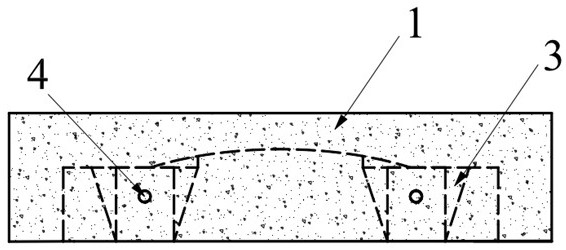
[0157] Straight bolt reserved hole 4;

[0158] The first reinforcing rib 3 is located at the reserved hole 4 for straight bolts;

[0159] The local reinforcement band 5 is located at the edge of the main body of the segment;

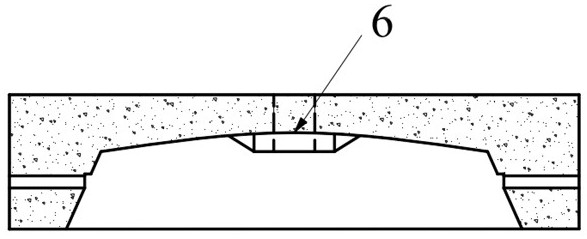
[0160] Segment grouting hole 6;

[0161] The second reinforcing rib 7 is located at the grouting hole 6 of the segment;

[0162] Hand hole 8, near the hand hole 8 is the concrete reinforcement area;

[0163] Local reinforcement with steel bars 9;

[0164] The soffit steel bar 10 is located in the soffit area of ​​the main body of the segment;

[0165] The spiral steel bar 11 is located at the grouting hole 6 of the segment.

[0166] 1) The soffit area of ​​the main body o...

Embodiment 2

[0179] A shield tunnel segment has an outer diameter of 6000mm and a ring width of 1500mm. The overall tunnel segment is made of ultra-high performance concrete material, the concrete grade is UC120, the steel bar type is HRB400, the thickness of the concrete cover layer is 20mm, the design load of the minimum reinforcement ratio is the maximum positive bending moment design value of 277.0kN·m, and the corresponding axial force design Value - 1867.5kN.

[0180] The design method of the main soffit area of ​​the soffit ultra-high performance concrete shield tunnel segment is as follows:

[0181] 1. According to the strength of the ultra-high performance concrete material used, the type of steel bar and the internal force generated by the external load calculated according to the code, the longitudinal normal section size of the segment is determined, and the thickness h of the vault is determined 1 and arch foot thickness h 2 .

[0182] Preliminary drafting of vault thicknes...


PUM


Abstract

Arch feet, steel mesh inside the concrete, pipe pipe grouting holes, tube seam grooves, and the horizontal cross section of the arched abdomen is a arc -surface structure; the arched abdomen also has an arched vertical cross section.For the design method of the present invention, the specific steps are as follows: 1) Determine the thickness H 1 And the thickness of the arch feet H 2 ; 2) Ultra -high -performance concrete pipes The main body of the arched belly area of the main cross -section bearing capacity calculation, the positive cross section of the arched belly area is equivalent to the rectangular section for reinforcement calculation;Calculation capacity calculation of the positive cross -section bending of the bending component and calculated by the carrier capacity of the positive cross bearing capacity of the positive cross -section of the compression component.The invention can solve the problem of poor cracking resistance of the tube.

Description

technical field [0001] The invention relates to the technical field of subway shield tunnel segment structures, in particular to a soffit type ultra-high performance concrete prefabricated shield tunnel segment structure; [0002] The present invention also relates to a design method for the above-mentioned segment structure. Background technique [0003] With the advancement of urbanization, the construction of urban rail transit tunnels in my country is advancing rapidly. As the main construction form of urban underground tunnel construction, shield tunneling method is widely used in the construction of urban underground space projects such as subways, underground pipe galleries and underground drainage channels. However, during the operation stage of the shield tunnel, the shield tunnel segments inevitably have different degrees of damage cracks, stress relaxation, and local damage to the joints, which eventually lead to engineering problems such as excessive deformation ...

Claims


Application Information

Patent Timeline
Patent Type & Authority Patents(China)
IPC IPC(8): E21D11/08E21D11/10G06F30/13G06F30/17
CPCE21D11/08E21D11/105G06F30/13G06F30/17
Inventor 陈仁朋吴怀娜冯东林刘源张阳孟凡衍程红战阮世强
Owner HUNAN UNIV
Why Eureka
Try Eureka