Temperature and calcium ion concentration two-parameter sensor and preparation method

A calcium ion, dual-parameter technology, used in thermometers, thermometers with physical/chemical changes, instruments, etc., can solve the problem of inability to achieve temperature and calcium ion concentration sensing accuracy requirements, low applicability of optical fiber sensors, and complex preparation process and other problems, to achieve the effect of spectral subdivision, simple structure and high sensitivity

Active Publication Date: 2021-04-30
BEIJING INFORMATION SCI & TECH UNIV
View PDF7 Cites 0 Cited by
  • Summary
  • Abstract
  • Description
  • Claims
  • Application Information

AI Technical Summary

Problems solved by technology

[0004] Traditional interferometric optical fiber sensor devices come in various forms, and the preparation process is often complicated, which cannot meet the accura

Method used


Image

  • Temperature and calcium ion concentration two-parameter sensor and preparation method
  • Temperature and calcium ion concentration two-parameter sensor and preparation method
  • Temperature and calcium ion concentration two-parameter sensor and preparation method

Examples


preparation example Construction

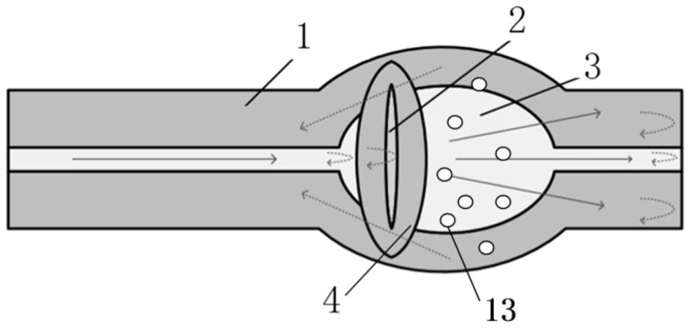
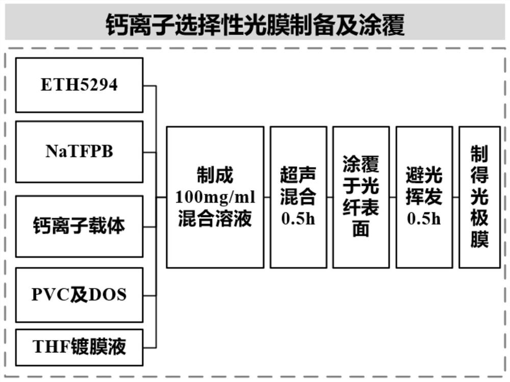
[0039] Such as Figure 1 to Figure 3 As shown, this embodiment provides a method for preparing a dual-parameter sensor of temperature and calcium ion concentration, which specifically includes the following steps: (a) preparing a thick cone interference structure 10 with an internal air fine cavity 13: step a1, combining two sections of single-mode The optical fiber is placed in the fusion splicer and welded by expanding the diameter of the light cone to form a thick cone; step a2, perform high-power instantaneous discharge on the thick cone, so that an air slit 2 is formed inside the thick cone; step a3, in the thick cone area Perform multiple discharges to form a thick cone structure containing the inner air fine cavity 13; (b) prepare the calcium ion selective photopolar film: step b1, the components of the calcium ion selective photode film of ETH5418 for the chromogenic ionophore The dosage is as follows, ETH5294 (5mmol / kg), NaTFPB (10mmol / kg), cation carrier (calcium ion...

Embodiment 1

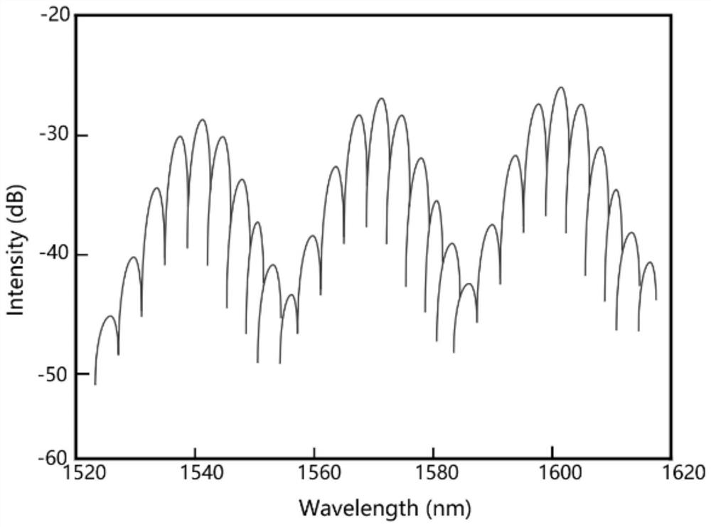
[0046] The optical fiber that the present invention adopts is the common single-mode optical fiber that model is SFM-28, cladding 1 diameter 125um, fiber core 3 diameter 9um, it is placed on the 80S high-precision single-core fusion splicer of Japanese Fujikura company on another SFM In the fusion splicer of -28 ordinary single-mode optical fibers, use the expanded diameter light cone fusion splicing mode to perform high-power instantaneous discharge to form an air slit 2 inside the thick cone, and perform multiple discharges in the thick cone area to form an internal The coarse cone structure of the air fine cavity forms an inner fine cavity with an axial cavity length of 6-7um and a radial length of the coarse cone cone area of ​​241um. That is to make the required thick cone interference structure 10 temperature calcium ion concentration dual parameter sensor structure. The spectrogram is the shape of a large envelope overlapping a small envelope, such as figure 2 shown. ...


PUM

PropertyMeasurementUnit
Film thicknessaaaaaaaaaa
Cladding diameteraaaaaaaaaa
Core diameteraaaaaaaaaa

Abstract

In order to realize simultaneous measurement of temperature and calcium ion concentration, the invention provides a temperature and calcium ion concentration two-parameter sensor based on an optical fiber inner cavity coarse cone interference structure. An inner cavity coarse cone structure is manufactured through optical fiber fusion discharge, and the end face of an optical fiber is modified with a calcium ion photoelectrode film in cooperation with a dilution spraying method. And the required optical fiber temperature and calcium ion concentration double-parameter sensor is manufactured. The sensor has the beneficial effects that the optical fiber interference structure is matched with the calcium ion photoelectrode, so that electrical logging interference of a traditional electrochemical method is avoided; the device is good in structural mechanical strength and reliable in stability; a three-beam interference structure can be realized, so that spectral subdivision is realized, and the measurement accuracy is improved.

Description

technical field [0001] The invention relates to an optical fiber device, in particular to a dual-parameter sensor of temperature and calcium ion concentration and a preparation method thereof. Background technique [0002] The optical fiber biosensor is mainly composed of a biological sensitive unit and an optical fiber. The biological active unit is used as the biological sensitive unit, and the optical fiber is used as a signal converter to express the degree of reaction between the target object and the sensitive element through electrical or optical signals, thereby obtaining the measured object. information. This method combines the advantages of optical fiber with mature biodetection technology, and is suitable for in vivo telemetry and online monitoring. [0003] Calcium ions, as the main electrolyte of the human body, are of great significance to various physiological activities of the body. However, in the existing calcium ion detection methods, it is difficult to...

Claims


Application Information

Patent Timeline
IPC IPC(8): G01K11/32G01N21/25G01N21/64G02B6/255
CPCG01K11/32G01N21/25G01N21/645G02B6/255G01N2021/6484
Inventor 祝连庆郝家祺张雯何巍何彦霖孙广开李红
Owner BEIJING INFORMATION SCI & TECH UNIV
Why Eureka
Try Eureka