Flow field measuring device and flow field measuring system

A measuring device and measuring system technology, which is applied in the direction of measuring device, fluid dynamics test, machine/structural component test, etc., can solve the problems of high maintenance cost and difficult wiring

Pending Publication Date: 2021-04-30
CHINA ELECTRONICS CORP 6TH RES INST
View PDF0 Cites 1 Cited by
  • Summary
  • Abstract
  • Description
  • Claims
  • Application Information

AI Technical Summary

Problems solved by technology

[0004] The purpose of the embodiments of the present application is to provide a flow field measurement device and a fl

Method used


Image

  • Flow field measuring device and flow field measuring system
  • Flow field measuring device and flow field measuring system
  • Flow field measuring device and flow field measuring system

Examples


Embodiment 1

[0039] In order to reduce the difficulty of wiring in an actual industrial production site and reduce maintenance costs, an embodiment of the present application provides a flow field measurement system and a flow field measurement device used in the system.

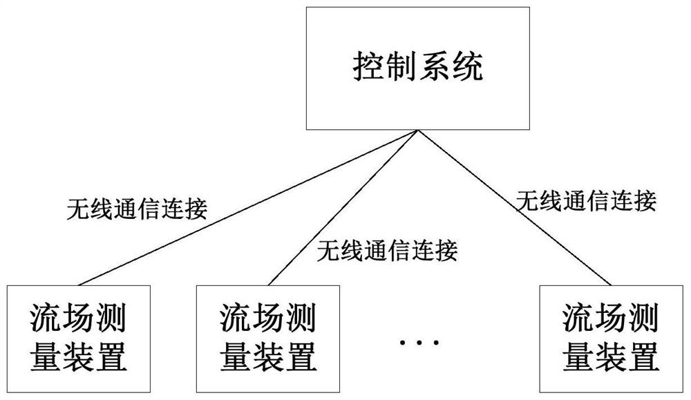
[0040] See figure 1 As shown, the flow field measurement system provided by the embodiment of the present application includes:

[0041] A plurality of flow field measuring devices are respectively arranged in each equipment to be tested.

[0042] The control system is wirelessly connected with each flow field measurement device to receive the flow field measurement information detected by each flow field measurement device.

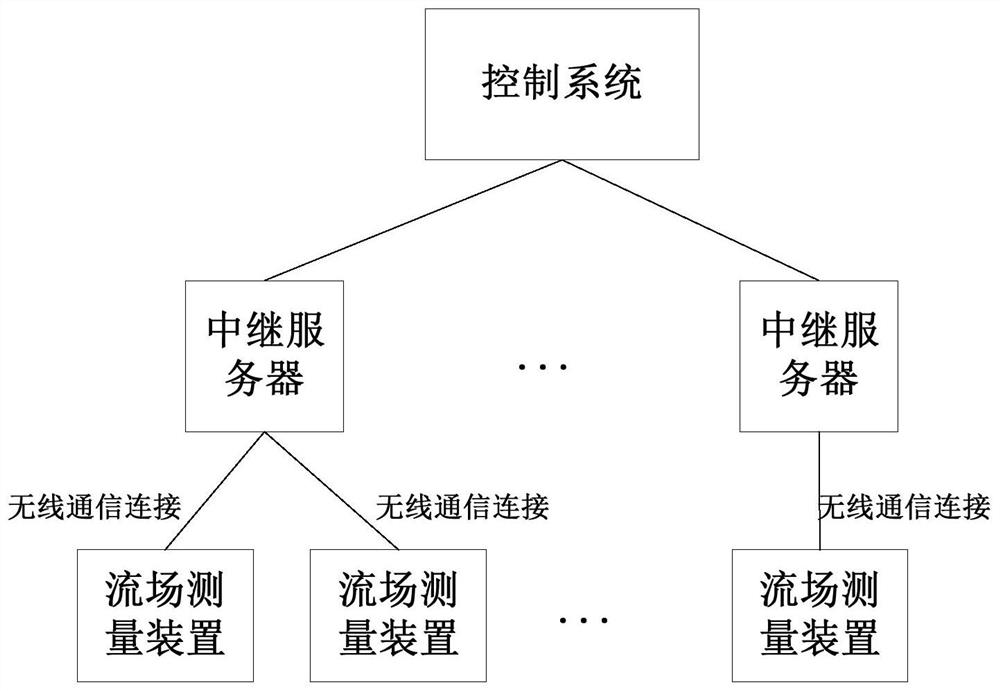
[0043] It should be noted that in practical applications, industrial production sites are often very large, and the distances between different devices under test are often not very close. Therefore, if the flow field measurement device is directly connected to the control system, depending on th...

Embodiment 2

[0087] On the basis of the first embodiment, the embodiment of the present application is described by taking a specific flow field measuring device and system structure applied in a thermal power plant as an example.

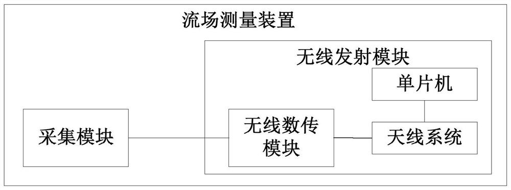
[0088] see Figure 8 as shown, Figure 8 It is a schematic structural diagram of a flow field measuring device provided in an embodiment of the present application, which includes: a sensing module (1), a data processing module (2) and a wireless transmitting module (3).

[0089] The casings of the three modules are made of corrosion-resistant stainless steel to adapt to the actual flue gas environment with high temperature, high dust and high corrosiveness; the casings of the three modules are fixedly connected by threads. The three modules are connected through plug-in terminals to realize mutual information exchange and power supply. Among them, the maximum diameter d of the flow field measurement device composed of three modules is less than or equal to 1...


PUM

PropertyMeasurementUnit
Diameteraaaaaaaaaa

Abstract

The embodiment of the invention provides a flow field measurement device and a flow field measurement system, and the device comprises an acquisition module which is used for sensing to-be-collected information in a flow field, and converting the sensed to-be-collected information into an electric signal; and a wireless transmitting module which comprises a wireless data transmitting module, a single chip microcomputer and an antenna system, wherein the wireless data transmitting module is connected with the acquisition module to obtain an electric signal and transmit the electric signal to the antenna system, the single-chip microcomputer is connected with the antenna system so as to control the antenna system to establish point-to-point data transmission connection with the target device, and the antenna system sends an electrical signal to the target device. Therefore, wireless transmission from the acquisition module to the target equipment is realized, a line between the flow field measurement device and the target equipment does not need to be arranged, the wiring difficulty is reduced, and meanwhile, a point-to-point transmission mode is established between the flow field measurement device and the target equipment, so when a transmission fault occurs, the fault communication link can be conveniently positioned by inquiring the fault information, so the maintenance cost is reduced.

Description

technical field [0001] The present application relates to the technical field of flow field measurement, and in particular, to a flow field measurement device and a flow field measurement system. Background technique [0002] At present, in scenarios such as thermal power plants, the measurement of flue gas flow velocity mainly uses measurement equipment such as pitot tubes and hot-wire anemometers to collect flow velocity, and then transmits the measured flow velocity signal to the control system (such as DCS (Distributed Control System, Distributed Control System), PLC (Programmable Logic Controller, Programmable Logic Controller)) to realize data exchange. [0003] However, the flow rate measurement realized by this kind of wired transmission method often has practical problems such as long transmission distance, complex site conditions, and difficult wiring in the actual industrial production site, which makes the implementation of the solution inconvenient. In addition...

Claims


Application Information

Patent Timeline
IPC IPC(8): G01M10/00
CPCG01M10/00
Inventor 王翔申志伟朱肖曼高松林许凤凯郭烁燕玮
Owner CHINA ELECTRONICS CORP 6TH RES INST
Why Eureka
Try Eureka