

Ventilation cooling equipment and method for avionics equipment
A kind of avionics equipment, ventilation and cooling technology, applied in the construction of electrical equipment components, separation methods, cleaning with electrostatic method, etc., can solve the problems of reducing electrical distance, taking a long time, destroying the insulation strength of electrical equipment, etc., to avoid failure , clean up fast effect
- Summary
- Abstract
- Description
- Claims
- Application Information
AI Technical Summary
Problems solved by technology
Method used
Image

Examples
Embodiment 1
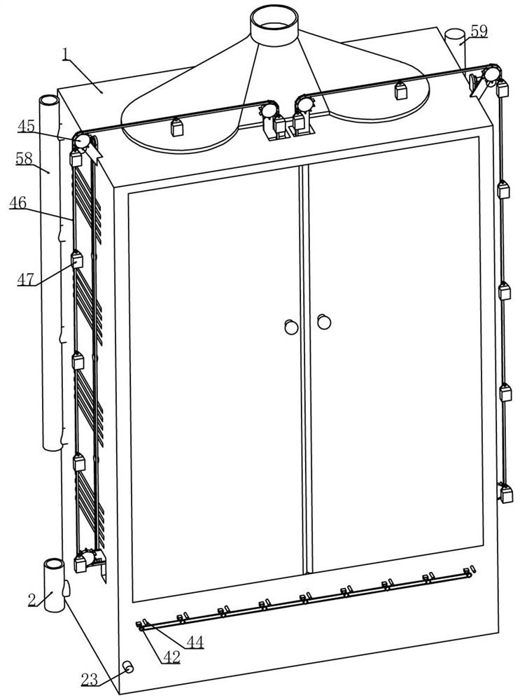
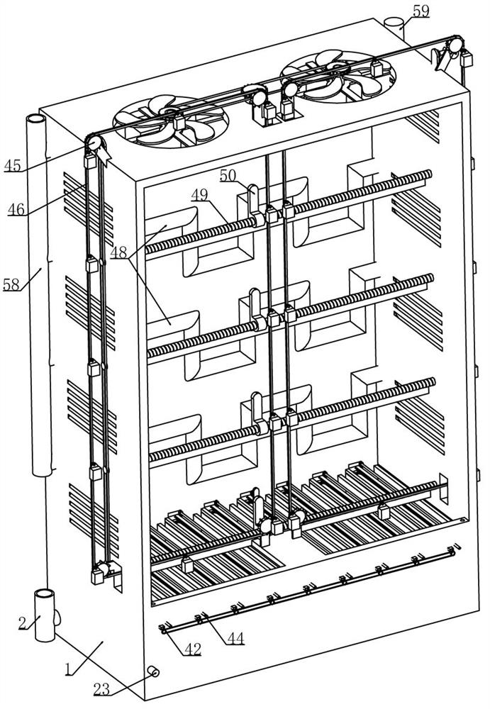
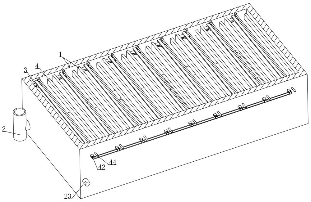
[0047] Embodiment 1, this embodiment provides a kind of ventilation and cooling equipment for avionics equipment, refer to the attached figure 1 , including the control cabinet 1 arranged in the bottom compartment of the aircraft (the control cabinet 1 is provided with a cabinet door, and the upper end of the control cabinet 1 is provided with a negative pressure device, so that the air in the control cabinet 1 is drawn to the gas exhaust pipe, The device is switched off during the cleaning process), see attached image 3 And attached Figure 4 As shown, we set a ventilation cooling pipe 2 on the bottom wall of the control cabinet 1 and a number of exhaust holes are arranged on the ventilation cooling pipe 2, and the outside air is transmitted into the ventilation cooling pipe 2 through the air compressor, or the cockpit is directly The cooling air inside is transmitted into the ventilation cooling pipe 2, and the electronic equipment is ventilated and cooled as a cooling con...
Embodiment 2
[0049] Embodiment 2, on the basis of Embodiment 1, when the first scraper 9 slides back and forth on the surface of the dust collecting plate 3 to clean up the dust, the dust still has a certain degree of adsorption due to the power off for a certain period of time. The dust falling off from the dust collection plate 3 will inevitably remain on the inclined surface of the plate 9. If it is not cleaned in time, the cleaning effect of the equipment will be reduced. Refer to the attached Figure 7 , attached Figure 8 And attached Figure 9 As shown, a second lead screw 12 is vertically rotated between the rotating shaft 10 and the connecting rod 8 on the scraper, and the second lead screw 12 is threaded to fit vertically with the inclined surface of the first scraper 9 The second scraper 13 of the first scraper 9, and the upper end of the first scraper 9 is provided with a support plate 14 that is longitudinally slidable with the control cabinet 1. On the support plate 14, a fa...
Embodiment 3
[0051] Embodiment 3, on the basis of embodiment 1, with reference to appended Figure 5 And attached Figure 6 As shown, the first drive device includes a drive lead screw 22 that is longitudinally rotatably installed below the first lead screw 5 at one end of the control cabinet 1, and the drive lead screw 22 is fixedly mounted on the side of the first chain drive in the control cabinet 1. Driven by the first motor 23, the first motor 23 is connected to an external power supply and is electrically connected to the controller. We screw the drive screw 22 with a drive helical rack 24 that is longitudinally slidable with the inner wall of the control cabinet 1 and drives the helical rack. The rack 24 is matched with a driving helical gear 25 that is rotatably installed on the lateral side of the control cabinet 1 close to the first motor 23, and the driving helical gear 25 is connected with a driving driving bevel gear 26 that is rotatably installed on the control cabinet 1 thro...
PUM
 Abstract
Description
Claims
Application Information