Internal energy integrated rectification device and rectification method using same

An internal energy and rectification technology, applied in the field of rectification, can solve the problems of underutilization of the heat of the rectification tower and low separation efficiency of the rectification tower, and achieve the improvement of the heat utilization rate, the separation efficiency and the reduction of the effective energy loss. Effect

Pending Publication Date: 2021-05-04
CHINA PETROLEUM & CHEM CORP +1
View PDF7 Cites 0 Cited by
  • Summary
  • Abstract
  • Description
  • Claims
  • Application Information

AI Technical Summary

Problems solved by technology

[0005] Aiming at the problems that the heat in the rectification tower of the current rectification device is not fully utilized, the gas in the stripping section enters the compressor with liquid, which affects the normal operation and life of the compressor, and the separation efficiency of the rectification tower is low, the present invention proposes an internal The energy-integrated rectification device fully optimizes the heat exchange process inside the rectification tower, fully improves the heat utilization rate, solves the problem that the gas enters the compressor with liquid and affects the normal operation and life of the compressor, and at the same time strengthens the gas-liquid two-way process. The contact of the phases in the column improves the separation efficiency of the rectification column

Method used


Image

  • Internal energy integrated rectification device and rectification method using same
  • Internal energy integrated rectification device and rectification method using same

Examples


Embodiment 1

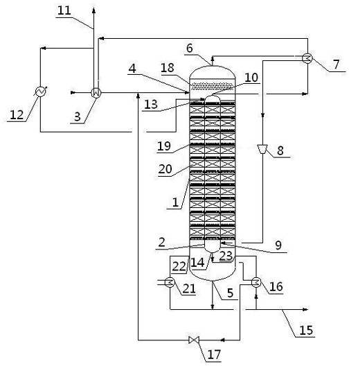
[0032] This embodiment discloses a rectification device with internal energy integration:

[0033] The rectification device includes a rectification tower with an inner and outer double-layer tower body, the outer tower body 1 is a stripping section, and the inner tower body 2 is a rectification section, which is arranged at the feed inlet I4 on the upper part of the outer tower body 1 The feed preheater 3 is externally connected, and the bottom of the outer tower body 1 is provided with a liquid outlet I5, a part of which is respectively connected to the discharge pipe 15 at the bottom of the tower and connected to the feed port V23 at the bottom of the outer tower body 1 through a reboiler 16 , the other part is connected to the feed port IV 22 located at the bottom of the outer tower body 1 through the auxiliary reboiler 21; the top of the outer tower body 1 is also provided with a gas outlet I6, which is connected to the compressor inlet superheater 7 and the compressor in ...

Embodiment 2

[0036] This embodiment discloses the method utilizing the device of embodiment 1 to carry out rectification:

[0037] After the feed is heated by the feed preheater 3, it enters the outer tower body 1 of the rectification tower through the feed inlet I4 for gas-liquid exchange. After the liquid phase is separated, the gas outlet I6 enters the compressor 8 through the compressor inlet superheater 7 to increase the pressure, and then enters the bottom of the inner tower body 2 through the feed inlet II9 to provide reboiling heat for the inner tower body 2; A part of the bottom liquid phase of the outer tower body 1 is discharged from the bottom discharge pipe 15 through the liquid outlet I5 and returned to the bottom of the outer tower body 1 by the feed inlet V23 after passing through the reboiler 16, which is the outer tower body 1 Provide reboil heat, part of which is returned to the bottom of the outer tower body 1 through the feed port IV 22 after the auxiliary reboiler 21,...

Embodiment 3

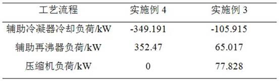
[0039] The present embodiment provides a kind of concrete process parameter and the result that utilize the method for embodiment 2 to carry out rectification:

[0040] The feed of the rectification tower is benzene-toluene system, the feed amount is 2000kg / h, the feed composition is 50% (wt%) benzene and 50% (wt%) toluene, the feed is fed at room temperature, and the feed preheater After preheating 3, the thermal condition of the feed is bubble point feed. The inner tower body 2 and the outer tower body 1 of the rectification tower are equipped with 10 layers of packing layers 20, the outer tower body 1 has an operating pressure of 1 atm, the operating temperature is 91 ° C, and the inner layer tower body 2 has an operating pressure of 3 atm. The operating temperature is 120° C., and the compression ratio of the compressor 8 is 3. The output of the tower top discharge pipe 11 is 1000kg / h, composed of 99.5% (wt%) benzene and 0.5% (wt%) toluene; the output of the tower bottom ...


PUM


Abstract

An internal energy integrated rectification device comprises a rectification tower with an inner layer tower body and an outer layer tower body, the outer layer tower body is a stripping section, the inner layer tower body is a rectification section, a feed inlet I formed in the upper portion of the outer layer tower body is externally connected with a feed preheater, a liquid outlet I is formed in the bottom of the outer layer tower body, and the liquid outlet I is connected with a tower bottom discharge pipe and connected with a feed inlet V after passing through a reboiler; a gas outlet I is formed in the top of the outer layer tower body, is externally connected with a compressor inlet superheater and a compressor in sequence, and is connected with a feeding hole II in the bottom of the inner layer tower body; a gas outlet II is formed in the top of the inner layer tower body, is externally connected with a compressor inlet superheater and a feeding preheater in sequence and then is connected with a tower top discharging pipe and a feeding hole III in the top of the inner layer tower body; a liquid outlet II is formed in the bottom of the inner layer tower body and is connected with a feeding hole I after passing through a reboiler and a throttling valve in sequence; a silk screen condensation plate is arranged below the top gas outlet I in the outer layer tower body; and liquid distribution devices and packing layers which are distributed at intervals are arranged in the outer layer tower body and the inner layer tower body. When the device is used for rectification, the effective energy loss in the rectification process is reduced, and the separation energy consumption is reduced.

Description

technical field [0001] The invention relates to a rectification device, in particular to a rectification device with internal energy integration, and belongs to the technical field of rectification. Background technique [0002] Distillation is the most widely used and most mature chemical separation technology. The main reason is that the rectification separation process usually only needs to provide energy separation agents, that is, heat and cooling, to obtain high-purity products, and the operation is simple, and the separation of mixed liquids of various concentrations can be easily realized. However, the rectification process uses thermal energy as the only separating agent, which consumes a large amount of high-temperature heat and outputs a large amount of low-temperature heat at the same time, so its energy consumption is high and the thermodynamic efficiency is extremely low. It is the most concentrated energy in the entire process and the entire chemical industry....

Claims


Application Information

Patent Timeline
Patent Type & Authority Applications(China)
IPC IPC(8): B01D3/14B01D3/32
CPCB01D3/143B01D3/32B01D3/322
Inventor 胡珺薄德臣陈建兵高明张英
Owner CHINA PETROLEUM & CHEM CORP
Why Eureka
Try Eureka