
Urban road surface flaw detection detector and terminal thereof

A detector and urban technology, applied in the field of detection instruments, can solve problems such as data band error, sensor and deflection basin out of contact, etc.

Pending Publication Date: 2021-05-04
BEIJING UNIV OF CIVIL ENG & ARCHITECTURE
View PDF1 Cites 0 Cited by
  • Summary
  • Abstract
  • Description
  • Claims
  • Application Information

AI Technical Summary

Problems solved by technology

[0005] However, in the above solution, the buffer layer component rebounds toward both ends after the pressure disappears. In view of this rebound method, the sensor will be out of contact with the deflection basin, or the device as a whole will rebound upwards, resulting in data errors.

Method used


Image

  • Urban road surface flaw detection detector and terminal thereof
  • Urban road surface flaw detection detector and terminal thereof
  • Urban road surface flaw detection detector and terminal thereof

Examples


Embodiment 1

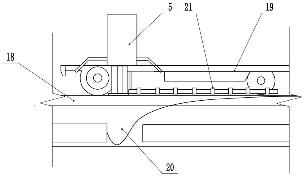
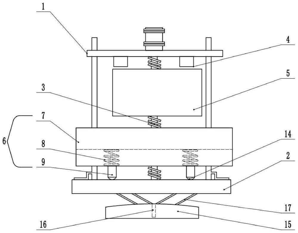
[0035] The embodiment is basically as attached figure 1 And attached figure 2 , as shown: a city road surface flaw detection detector is connected to the tractor 19 of the driving ground 18, including a load-stabilizing platform 1 located above and a bearing platform 2 located below, and a vertical The stroke rod 3 in the direction, the stable load platform 1 has an electromagnet 4 to control the lifting and falling of the gravity hammer 5, the stroke rod 3 wraps the gravity hammer 5, and the surface of the bearing platform 2 is provided with a buffer assembly 6.

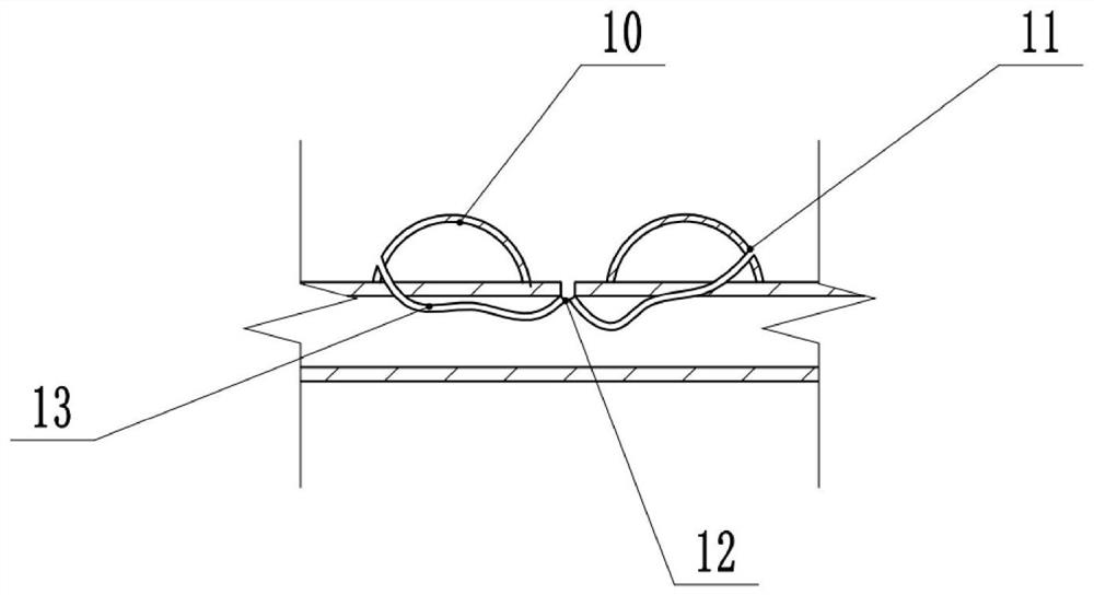
[0036] Please refer to image 3 and Figure 4 , the buffer assembly 6 is divided into rubber layer 7, extension spring layer 8 and point contact layer 9 from top to bottom, extension spring layer 8 has several groups of opposite extension springs, and rubber layer 7 has cylindrical protrusions 10. The protrusions 10 form a rectangular matrix along the center of the rubber layer 7. The protrusions 10 are located ...

Embodiment 2

[0043] The difference between this embodiment and the above-mentioned embodiments is that this embodiment discloses an urban road surface flaw detection detection terminal including a deformation sensor 21, a data processor, a memory, and an output device. The number of deformation sensors 21 is 8, and the deformation sensor The device 21 is connected with a measuring beam, and the deformation sensor 21 is distributed in-line around the first sensor 16, and the data memory is connected in parallel with the memory, the deformation sensor 21, the center sensor and the output device, and the output device includes a display and a printer, and the travel lever 3 Adopt hydraulic rod.

[0044] The specific implementation process is as follows: adjust the mass and height of the gravity hammer 5, and control the weight to be loaded to the fourth-level load, then arrange the measuring points on the road surface, lower the side beams when the measuring points are arranged, so as to distr...


PUM


Abstract

The invention discloses an urban road surface flaw detection detector and a terminal thereof in the field of detection instruments, and aims to overcome the defect that a sensor is separated from a deflection basin due to the fact that the return direction of a buffer assembly is not specific in the prior art. In order to overcome the problem, according to the technical scheme, the urban road surface flaw detection detector comprises a stable loading platform located on the upper portion and a bearing table located on the lower portion, a stroke rod is wrapped by a gravity hammer, and a buffer assembly is arranged on the surface of the bearing table; the buffer assembly is sequentially divided into a rubber layer, a tension spring layer and a point contact layer from top to bottom, a plurality of oppositely-arranged tension springs are arranged in the tension spring layer, the rubber layer is provided with cylindrical protrusions, the protrusions define a rectangular matrix along the center of the rubber layer, and due to the fact that the contact time of the gravity hammer and the rubber layer is prolonged, the return direction of the tension springs is limited; therefore, when the tension springs return, the tension springs can only return in the direction away from the rubber layer, meanwhile, the measurement time of a first sensor is prolonged, and the correctness of data collection is facilitated.

Description

technical field [0001] The invention belongs to the field of detection instruments, in particular to an urban pavement flaw detection detector and a terminal thereof. Background technique [0002] With the increase of expressway mileage in our country year by year, people pay more and more attention to the scientific management of expressways. An important indicator of pavement technical design is the allowable deflection value. Falling Weight Deflectometer (FWD), a dynamic testing equipment, has been more and more recognized for the non-destructive testing of subgrade and pavement deflection, and a lot of achievements have been made in the development and application of FWD. FWD measures the dynamic deflection of the pavement, and can back-calculate the modulus of resilience of the pavement. my country's "Highway Subgrade Pavement Field Test Regulations" (III059-95) has also listed FWD as a deflection testing equipment. It is important to use FWD for further development, ...

Claims


Application Information

Patent Timeline
Patent Type & Authority Applications(China)
IPC IPC(8): G01N3/303G01N3/62G01N3/02E01C23/01
CPCE01C23/01G01N3/02G01N3/303G01N3/62G01N2203/0039
Inventor 彭培火
Owner BEIJING UNIV OF CIVIL ENG & ARCHITECTURE
Learn More