A Piezoelectric Synchronously Tuned ECDL Laser Based on Sector Ring Structure

A synchronous tuning and fan-ring technology, applied to lasers, laser components, semiconductor lasers, etc., can solve problems such as complexity, not compact structure, unstable output wavelength of lasers, and broadening of line width, so as to optimize vibration resistance and improve reliability performance, size reduction effect

Active Publication Date: 2022-03-11
NAT UNIV OF DEFENSE TECH
View PDF6 Cites 0 Cited by
  • Summary
  • Abstract
  • Description
  • Claims
  • Application Information

AI Technical Summary

Problems solved by technology

[0004] The mode-hopping behavior of the laser will greatly reduce the robustness of the external cavity semiconductor laser. At the same time, due to the mode-hopping, the output wavelength of the laser cannot continuously scan all the wavelengths in a certain band, which brings great advantages to its application in engineering. come with great limitations
The synchronous tuning of the Littman grating external cavity semiconductor laser can be realized by selecting the rotation axis point of the reflective tuning mirror. The rotation point that satisfies the synchronous tuning is called the best tuning point, which is located at the angle between the grating plane and the extension line of the rear end face of the diode. At the intersection of the bisector and the reflective tuning mirror, its position is relatively far away from other optical components. If the traditional cantilever beam structure is used to solve the problem of the reflective tuning mirror rotating around the axis point, the structure is usually not compact enough due to the use of long arms or is too complicated
In addition, the long spiral arm is very sensitive to external vibration and interference, which will bring the shortcomings of laser output wavelength instability and line width broadening

Method used


Image

  • A Piezoelectric Synchronously Tuned ECDL Laser Based on Sector Ring Structure
  • A Piezoelectric Synchronously Tuned ECDL Laser Based on Sector Ring Structure
  • A Piezoelectric Synchronously Tuned ECDL Laser Based on Sector Ring Structure

Examples


Embodiment Construction

[0028]The technical solution of the present invention will be clearly and completely described through examples below.

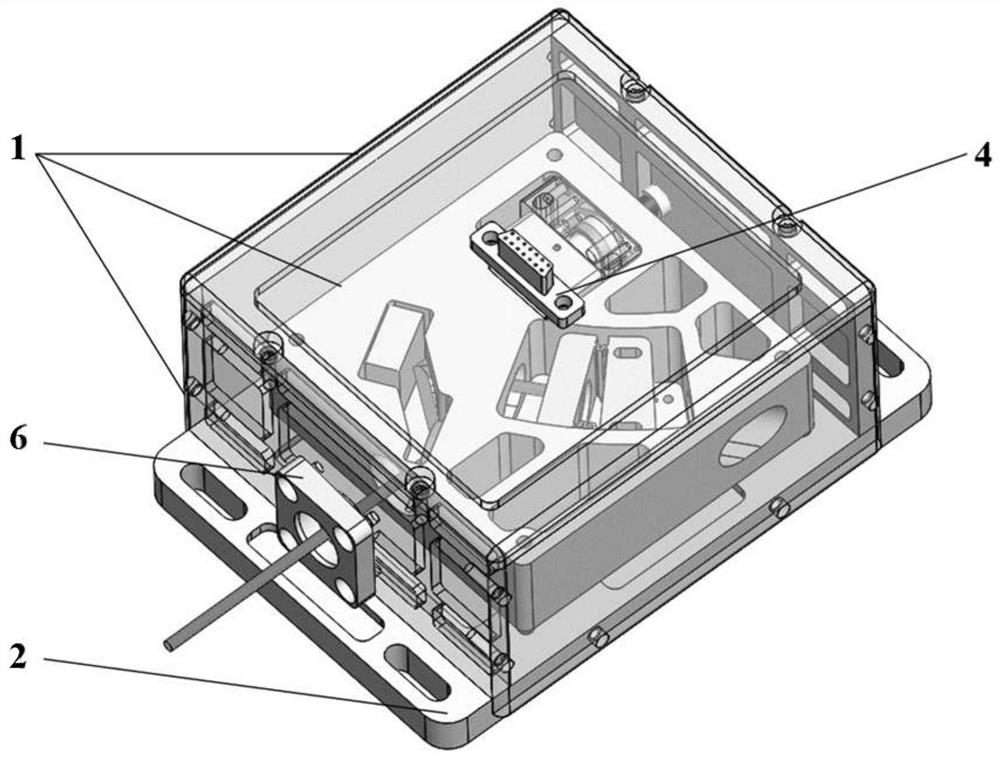
[0029] figure 1 A schematic diagram of the overall appearance of the ECDL laser described in the present invention is shown.

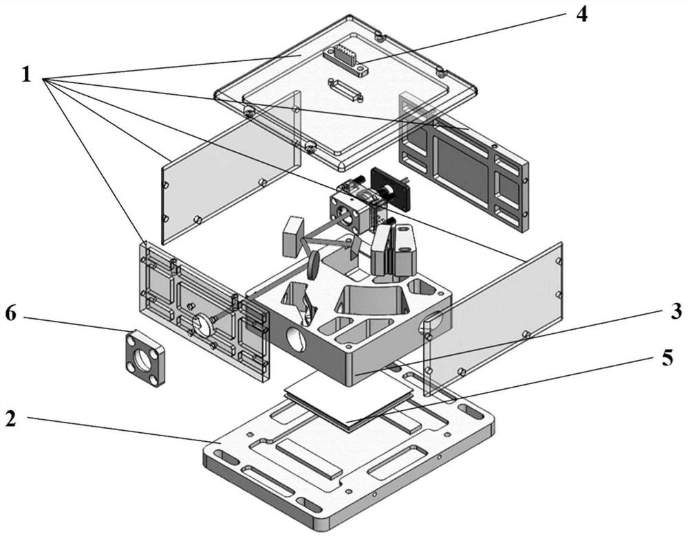
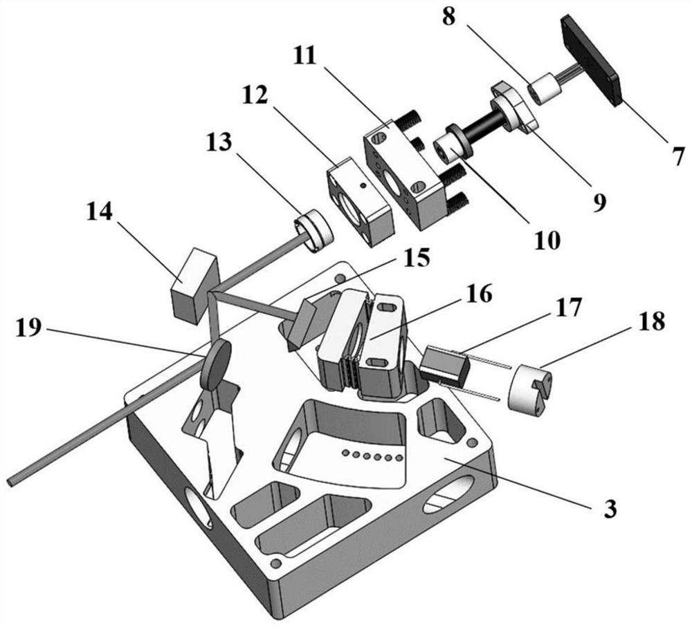
[0030] figure 2 The exploded disassembly diagram of the ECDL laser according to the present invention is shown: including the laser shell 1, the laser outer bottom plate 2, the fan ring guide rail bottom plate 3, the controller interface 4, the temperature control ceramic 5, the output window 6, thermistor, and the current interface Board 7, laser diode pin socket 8, laser diode pressure ring 9, laser diode 10, laser diode holder 11, collimator lens holder 12, collimator lens 13, reflective grating 14, right-angle prism 15, fan ring tuning bracket 16. Piezoelectric ceramics 17, piezoelectric ceramic mounting sleeves 18, high reflection mirrors 19;

[0031] The laser housing 1 includes a front plate, a rear plate, two side plates ...


PUM


Abstract

The invention belongs to the technical field of semiconductor lasers, and relates to a piezoelectric synchronously tuned ECDL (External Cavity Diode Laser) laser based on a sector ring structure. The invention consists of a laser shell, a laser outer bottom plate, a fan ring guide rail bottom plate, a controller interface, a temperature control ceramic, an output window, a thermistor, a current interface board, a laser diode pin socket, a laser diode pin socket, and a laser diode pressure ring , laser diode, laser diode holder, collimating lens holder, collimating lens, reflective grating, right-angle prism, fan ring tuning bracket, piezoelectric ceramics, piezoelectric ceramic mounting sleeve, high reflection mirror; the present invention utilizes fan ring The unique design of the guide rail satisfies the synchronous tuning conditions of ECDL. It can not only achieve a wide range of mode-hop-free tuning, but also reduce the size of the laser and significantly improve the reliability of the laser, making it suitable for some special environments such as aviation, Aerospace, weapons and equipment applications and other fields of requirements.

Description

technical field [0001] The invention relates to a piezoelectric synchronously tuned ECDL (External Cavity Diode Laser) laser based on a sector ring structure, and belongs to the technical field of external cavity semiconductor lasers. Background technique [0002] External-cavity semiconductor lasers provide a cheap and reliable tunable laser source. They usually use gratings as external cavities to provide external optical feedback into the active region of semiconductors, which can greatly improve the spectral performance of semiconductor lasers and obtain narrower linewidths. Higher spectral purity and wider continuous tuning range provide ideal coherent light sources for high-resolution spectroscopy, quantum precision measurement, optical communication, and lidar. [0003] Synchronous tuning is also called continuous mode-hop-free tuning, and its range is a key indicator for evaluating the performance of external cavity semiconductor lasers. Synchronously tunable externa...

Claims


Application Information

Patent Timeline
Patent Type & Authority Patents(China)
IPC IPC(8): H01S5/023H01S5/02253H01S5/14
CPCH01S5/141
Inventor 邹宏新詹子豪王文海
Owner NAT UNIV OF DEFENSE TECH
Why Eureka
Try Eureka