Air compressor for fuel cell
A fuel cell and air compressor technology, which is applied to liquid fuel engines, mechanical equipment, machines/engines, etc., can solve the problems of large air aerodynamic loss, increased aerodynamic power consumption, unfavorable miniaturization of air compressors, etc., and achieves compact structure. Effect
- Summary
- Abstract
- Description
- Claims
- Application Information
AI Technical Summary
Problems solved by technology
Method used
Image
Examples
Embodiment 1
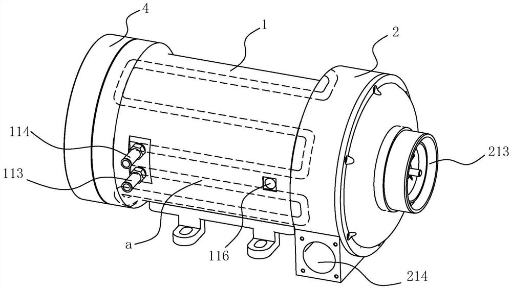
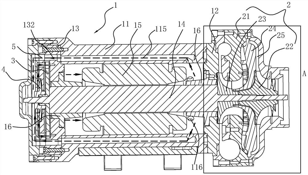
[0040] Depend on Figure 1 to Figure 7 Commonly shown, the fuel cell air compressor disclosed in this embodiment includes a motor 1 and a compressor 2 . The motor 1 includes a casing 11 with openings at both ends, end covers (respectively a first end cover 12 and a second end cover 13) arranged at both ends of the casing 11, both ends are connected to corresponding The end covers are rotatably connected and pass through the motor shaft 14 outside the corresponding end cover and the stator 15 disposed in the casing 11 and surrounding the motor shaft 14 . Wherein, this embodiment does not limit the specific structure of the radial dynamic pressure air bearing 16 .
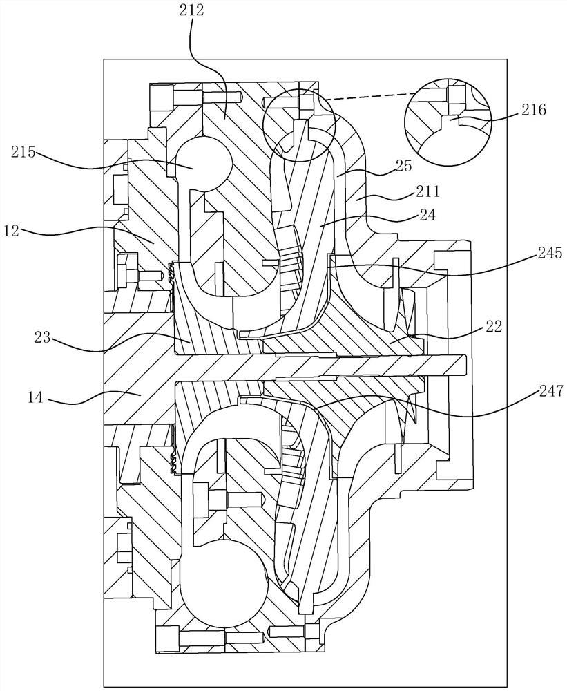
[0041] The compressor 2 in the present embodiment comprises the compressor case 21 that is provided with cavity, low-pressure stage compressor wheel 22 and high-pressure stage compressor wheel 23; One end of the compressor case 21 is fixed with the first end cover 12, and the other end An air inlet 213 is provided,...
Embodiment 2
[0052] The difference between this embodiment and the first embodiment is that the air cooling device 4 is omitted, and a turbine energy recovery device 6 is added at its installation position to realize energy recovery and reduce power consumption.
[0053] Depend on Figure 12As shown, the turbine energy recovery device 6 includes a turbine casing 61, a turbine 62 and an actuator 63 (can directly adopt an existing actuator) for adjusting the nozzle ring blade angle of the turbine 62; one end of the turbine casing 61 is connected to the casing 11 Fixed connection, the other end is provided with waste gas outlet 611; The periphery of turbine shell 61 is provided with waste gas inlet (not shown in the figure), and turbine 62 is fixed with the motor shaft 14 that passes through thrust structure 3 and stretches into the turbine shell 61 The connection adopts a direct drive method, without the need to increase the transmission device, and reduces the transmission loss. The exhaus...
PUM
 Abstract
Description
Claims
Application Information
 - R&D
- Intellectual Property
- Life Sciences
- Materials
- Tech Scout
- Unparalleled Data Quality
- Higher Quality Content
- 60% Fewer Hallucinations
Browse by: Latest US Patents, China's latest patents, Technical Efficacy Thesaurus, Application Domain, Technology Topic, Popular Technical Reports.
© 2025 PatSnap. All rights reserved.Legal|Privacy policy|Modern Slavery Act Transparency Statement|Sitemap|About US| Contact US: help@patsnap.com


