
Multifunctional intelligent drying system and drying process

A drying system and multi-functional technology, applied in drying safety systems, drying, dryers, etc., can solve the problems of unstable temperature, no automatic control, unstable dry humidity, etc.

Pending Publication Date: 2021-05-07
吉林市恒远机制木炭有限公司
View PDF0 Cites 3 Cited by
  • Summary
  • Abstract
  • Description
  • Claims
  • Application Information

AI Technical Summary

Problems solved by technology

[0002] The drying line is a mechanical combination equipment that uses hot air flow to reduce moisture. It is used to dry materials. The dryer vaporizes and overflows the moisture in the material through the heated hot air flow to obtain the required moisture content percentage. The purpose of the dryer is to meet the needs of material use and further processing. With the development of society, drying lines are used more and more widely in people's daily production and life, but the current drying lines are manually controlled by manual experience. Combination of multiple equipment, manual operation process is relatively complicated, manual ignition, manual fuel addition, manual activation of buttons for various equipment, manual adjustment of dry humidity, etc.
The deficiencies of manual control mainly include the following points: when refueling, the furnace door must be opened and closed, and the temperature is unstable due to the entry of cold air; the amount of refueling is difficult to control, and the amount of fuel added directly affects the stability of the temperature; The dry humidity is unstable; according to the change of temperature and dry humidity, it is difficult to control the amount of incoming raw materials, resulting in unstable dry humidity; the temperature of raw materials will rise sharply, without automatic control and alarm prompts, once negligent, it is easy to cause damage to the inside of the dryer. Catching Fire, Drain Flames, Causing Severe Damage

Method used


Image

  • Multifunctional intelligent drying system and drying process
  • Multifunctional intelligent drying system and drying process
  • Multifunctional intelligent drying system and drying process

Examples


Embodiment 1

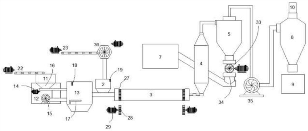
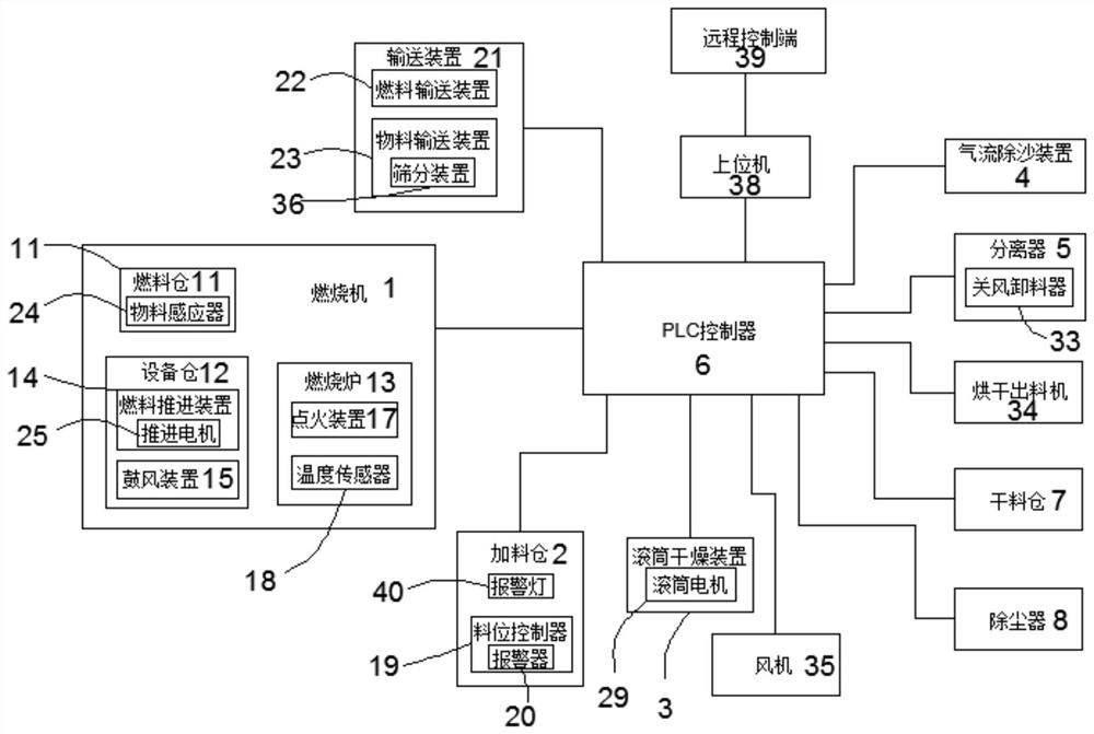
[0038] Such as figure 1 and 2 As shown, this embodiment provides a multifunctional intelligent drying system, which includes a burner 1, a feeding bin 2, a drum drying device 3, an airflow desanding device 4, a separator 5 and a PLC controller 6 connected in sequence. The separator 5 is connected to a dry storage bin 7 and a dust collector 8 respectively. The PLC controller 6 is respectively connected with the burner 1, the feeding bin 2, the drum drying device 3, the airflow desanding device 4, the separator 5, the dry material bin 7, the Dust collector 8 is connected.

[0039]The drying system also includes a conveying device 21, the conveying device 21 includes a fuel conveying device 22 and a material conveying device 23, the fuel conveying device 22 is connected to the fuel bin 11, and the material conveying device 23 and the material conveying device 23 are connected to each other. The feeding bin 2 is connected to each other, and the fuel conveying device 22 and the ...

Embodiment 2

[0050] This embodiment provides a multifunctional intelligent drying system. The difference from Embodiment 1 is that the drying system also includes a host computer 38 and a remote control terminal 39 connected to the host computer 38 through a communication device. The upper computer 38 is connected with the PLC controller 6 . The communication device includes at least one of a 2G / 3G / 4G / 5G network module, a PLC power line carrier module, NB-IoT, and a LoRa low-power wide-area network module. This kind of remote operation method can be implemented in areas with stable network. According to the temperature and moisture content of raw materials in various places, simple programming can truly realize one-button fool-like operation.

Embodiment 3

[0052] The invention provides a drying process of a multifunctional intelligent drying system. The material to be dried is a biomass stick, which is also a good fuel, and its moisture content is generally controlled at 6-12%, and controlled at 8 -9% is the best, so the fuel used in this embodiment except for the first time is directly dried biomass sticks, and the drying process is as follows:

[0053] Step 1. The fuel is delivered to the burner through the fuel delivery device for combustion to generate heat energy, and the heat energy is delivered to the drum drying device; other fuels need to be added to the burner during the first operation, and the biomass sticks are dried and put into the dry storage bin Finally, the fuel delivery device is directly connected to the dry storage bin, and the biomass sticks in the dry storage bin are transported to the burner as the fuel for the subsequent drying process;

[0054] Step 2, transport the biomass sticks to be dried to the fee...


PUM


Abstract

The invention provides a multifunctional intelligent drying system and a drying process. The system comprises a combustor, a feeding bin, a roller drying device, an airflow sand removing device, a separator and a PLC, all of which are connected in sequence. The separator is connected with a dry material bin and a dust remover. The PLC is connected with the above mechanisms. The combustor comprises a fuel bin, an equipment bin and a combustion furnace, the fuel bin is located above the equipment bin, a fuel propelling device and a blower device are arranged in the equipment bin, and the fuel propelling device is connected with a discharging port of the fuel bin. The fuel propelling device and the blower device are respectively connected with the combustion furnace through pipelines, and an ignition device and a temperature sensor are arranged in the combustion furnace. A material level controller is arranged in the feeding bin and provided with an alarm, and an alarm lamp is arranged outside the feeding bin. The drying system further comprises a conveying device, the conveying device comprises a fuel conveying device and a material conveying device, the fuel conveying device is connected with the fuel bin, and the material conveying device is connected with the feeding bin.

Description

technical field [0001] The invention belongs to the technical field of drying equipment, and in particular relates to a multifunctional intelligent drying system and a drying process. Background technique [0002] The drying line is a mechanical combination equipment that uses hot air flow to reduce moisture. It is used to dry materials. The dryer vaporizes and overflows the moisture in the material through the heated hot air flow to obtain the required moisture content percentage. The purpose of the dryer is to meet the needs of material use and further processing. With the development of society, drying lines are used more and more widely in people's daily production and life, but the current drying lines are manually controlled by manual experience. Combination of multiple equipment, manual operation process is relatively complicated, manual ignition, manual fuel addition, manual activation of buttons for various equipment, manual adjustment of dry humidity, etc. The def...

Claims


Application Information

Patent Timeline
Patent Type & Authority Applications(China)
IPC IPC(8): F26B11/04F26B23/02F26B25/00F26B25/02
CPCF26B11/0436F26B23/02F26B25/002F26B25/007F26B25/009F26B25/02
Inventor 黄敬喜
Owner 吉林市恒远机制木炭有限公司
Learn More