Air conditioner

A technology for air conditioners and air conditioner loads, applied in refrigerators, high-efficiency regulation technology, AC motor control, etc., and can solve problems such as taking into account the factors of refrigerant increase, large compressor vibration, and small current value.

Inactive Publication Date: 2003-11-12
KK TOSHIBA
View PDF0 Cites 0 Cited by
  • Summary
  • Abstract
  • Description
  • Claims
  • Application Information

AI Technical Summary

Problems solved by technology

[0004] In the above-mentioned conventional start-up control operation, from point A at start-up to point C maintained for stabilizing the refrigerating cycle, as the frequency time change rate for raising the output frequency of the power conversion device, the rate of change in relation to the air-conditioning load is used. Change the rate of change when the frequency is changed accordingly, for example, a small time rate of change of about 1Hz / sec is used, so there is a problem of large vibration of the compressor
[0005] In addition, since point A at start-up is set to the frequency corresponding to the lowest rotational speed in the speed control range, when the lowest frequency is set high, a large current will flow through the switching elements such as GTR, so it may occasionally occur The switching element destroys the problem
[0006] In addition, in the traditional start-up control, when determining the start-up frequency at point A, the load increase factors such as the residual amount of refrigerant in the compressor and the outside air temperature are not taken into consideration, and these will also cause damage to the switching element. factor
[0007] On the other hand, when the frequency at point A at start-up, that is, the lowest frequency in the speed control range, is set low, there is a problem that even when operating in a phase-open state in which one phase of the three-phase power supply is disconnected, the Because the current value is too small, the overcurrent protection circuit does not operate

Method used


Image

  • Air conditioner
  • Air conditioner
  • Air conditioner

Examples


Embodiment Construction

[0032] The present invention will be described in detail below according to the preferred embodiment shown in the accompanying drawings.

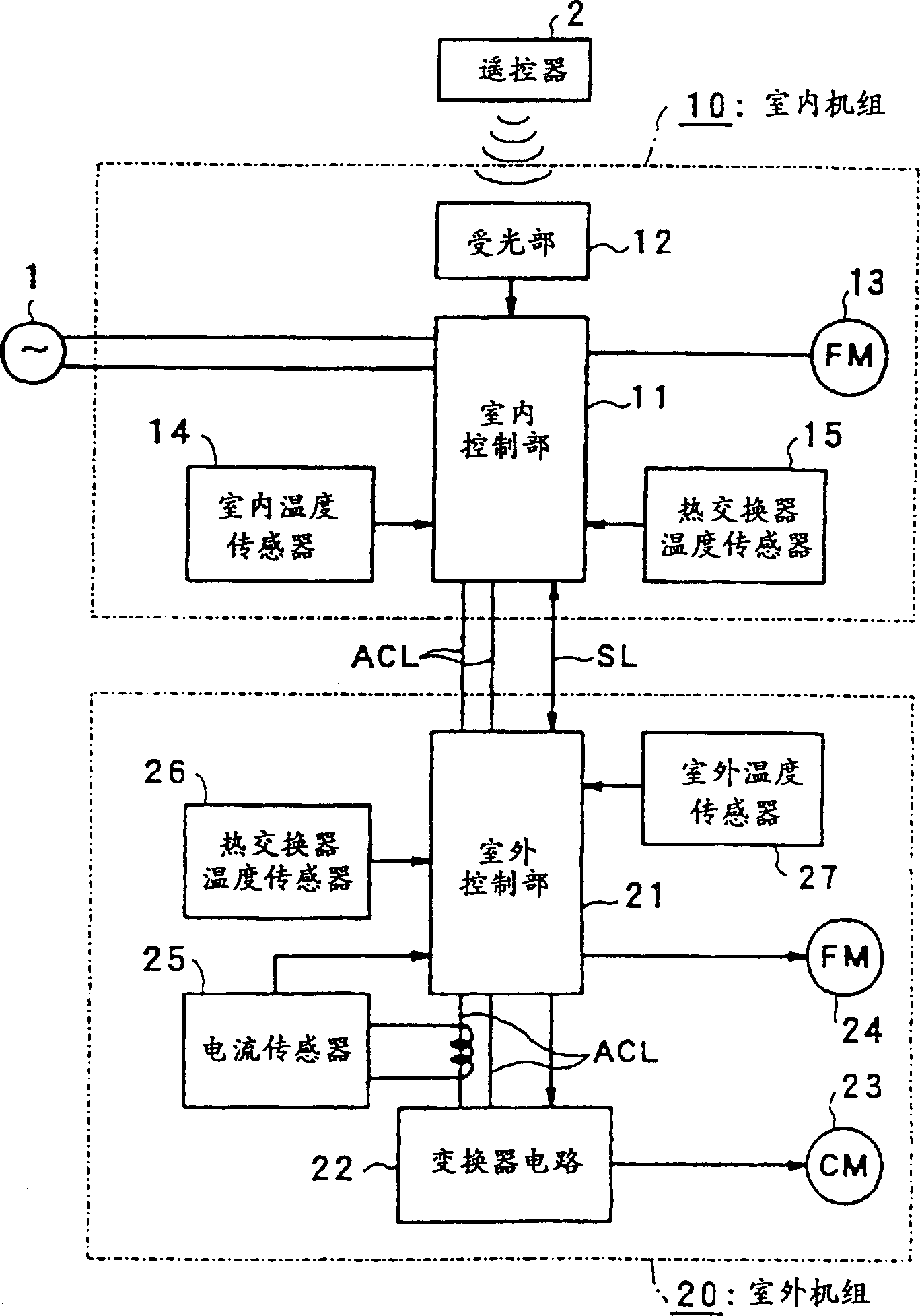
[0033] figure 1It is a block diagram showing the schematic configuration of the control system according to the first embodiment of the present invention. In this figure, 1 is a single-phase AC power supply, and 2 is a remote control device. The indoor unit 10 is connected to the single-phase AC power supply 1 , and an infrared control signal is sent from the remote control device 2 . The indoor unit 10 includes: an indoor control unit 11 including a microcomputer as a control means, receives the signal from the remote control device 2 and adds the signal to the light receiving unit 12 on the indoor control unit 11, and the indoor control unit 11 controls the speed. The controlled indoor fan motor 13 detects the indoor temperature and supplies it to the indoor temperature sensor 14 of the indoor control unit 11 , and detects the indoor h...


PUM


Abstract

The invention is to prevent a switching element for constituting a power-converting device from being damaged, and at the same time to suppress vibration on activation. In an air conditioner where a compressor is driven by a power- converting device whose output frequency is variable, and at the same time the output frequency of the power-converting device is changed with a preset frequency range and a time change rate corresponding to an air-conditioning load, a control means for controlling the output frequency of the power- converting device is provided so that the output frequency rises from an activation frequency that is lower than the lowest value of the frequency range by a specific value to the lowest value of the frequency range on activation in a heating operation mode.

Description

technical field [0001] The present invention relates to an air conditioner in which a compressor is driven by a power conversion device with a variable output frequency and the output frequency is varied according to the air conditioner load. Background technique [0002] This kind of power conversion device, which is generally called a converter, converts the AC current at the primary side into DC, and then converts it into a necessary frequency through the on and off of a high-power transistor (hereinafter referred to as GTR) as a switching element, and then sends it to the secondary side. The output device is becoming a common means of load control method using speed control. [0003] Figure 9 It is a graph showing the relationship between the time t and the output frequency F of the power conversion device when the start-up control operation is performed by the power conversion device. As is well known, the output frequency of the power conversion device is determined ...

Claims


Application Information

Patent Timeline
Patent Type & Authority Patents(China)
IPC IPC(8): H02P1/30F24F11/00F24F11/02H02P27/06
CPCY02B30/741F25B2500/26F25B2600/021Y02B30/70
Inventor 菊川元嗣渡边佳则
Owner KK TOSHIBA
Why Eureka
Try Eureka