Rotatable truss and strength resistance evaluation method thereof
A truss and strength technology, applied in the field of rotatable truss and its strength resistance assessment, can solve the problems of inconvenient replacement and inability to assess strength, achieve the effect of anti-corrosion thermodynamic performance and improve safety
- Summary
- Abstract
- Description
- Claims
- Application Information
AI Technical Summary
Problems solved by technology
Method used
Image
Examples
Embodiment 1
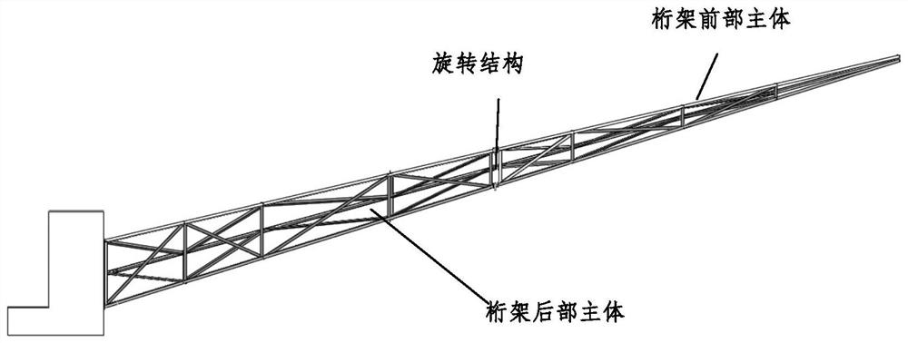
[0067] The truss support includes a truss main body, a top interface and a fixing device; wherein, the truss main body is divided into a truss rear main body, a truss front main body and a rotating structure. After connecting with the pile foundation, the overall effect is as follows figure 1 shown.
[0068] The main body of the truss is made of pultruded carbon fiber reinforced composite material, the main beam of the rear main body of the truss is a square beam, and the front main body of the truss and the diagonal support rods are equilateral angle beams. The composite material is composed of carbon fibers and a matrix, and is black after curing.
[0069] Among them, carbon fiber T300 composite material is a high-performance aerospace-grade composite material, which has the characteristics of light weight, high strength, high temperature resistance, corrosion resistance and excellent thermodynamic properties, so it is widely used as structural materials and high temperatur...
Embodiment 2
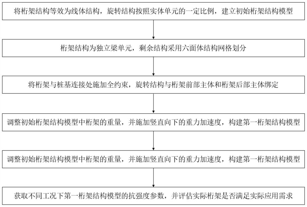
[0079] In the strength evaluation method provided in Example 2, the truss structure used is the truss structure provided in Example 1. In order to ensure the safety of the truss, it is necessary to use the large-scale finite element software ABAQUS to simulate and analyze the structural strength of the truss under working and installation conditions to determine whether the structural strength meets the requirements. Among them, the unit in the simulation calculation uses the N-mm unit system. Among them, the basic mechanical properties of composite materials and stainless steel are shown in the table.
[0080]
[0081] Step 1: Calculate model simplification
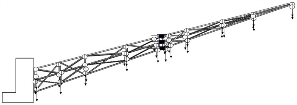
[0082] The initial truss structure model includes 6 main girders, oblique support rods and top braces in the front and rear main bodies of the truss. In the process of finite element analysis, ABAQUS software treats the truss structure as a beam structure. In order to facilitate modeling and calculation during analy...
Embodiment 3
[0097] The strength evaluation method provided in embodiment 3, the truss structure adopted is the truss structure provided in embodiment 1, which is similar to the strength evaluation method provided in embodiment 2, the difference is that embodiment 2 evaluates the truss structure under working conditions Strength parameters, embodiment 3 evaluates the resistance strength parameters under the installation condition of the truss structure. Details are as follows:
[0098] Such as Figure 7 As shown, the truss installation condition: the truss structure requires installers to install and remove the fixing pins at the rotating structure; the material parameters under the truss installation condition are the same as those of the carbon fiber T300 under the working condition in Example 2.
[0099] Step 1: Calculate model simplification
[0100] Based on the installation conditions, the most dangerous situation of the truss bearing is considered, that is, the fixed pin of the ro...
PUM
| Property | Measurement | Unit |
|---|---|---|
| Diameter | aaaaa | aaaaa |
| Diameter | aaaaa | aaaaa |
| Vertical height | aaaaa | aaaaa |
Abstract
Description
Claims
Application Information
 - R&D
- Intellectual Property
- Life Sciences
- Materials
- Tech Scout
- Unparalleled Data Quality
- Higher Quality Content
- 60% Fewer Hallucinations
Browse by: Latest US Patents, China's latest patents, Technical Efficacy Thesaurus, Application Domain, Technology Topic, Popular Technical Reports.
© 2025 PatSnap. All rights reserved.Legal|Privacy policy|Modern Slavery Act Transparency Statement|Sitemap|About US| Contact US: help@patsnap.com


