Odor purification device

A technology for purifying device and odor, which can be used in combination devices, air quality improvement, chemical instruments and methods, etc., and can solve problems such as difficult governance, air quality impact, and artificial work affecting the surrounding environment.

Active Publication Date: 2021-05-11
宇星环保工程有限公司
View PDF10 Cites 1 Cited by
  • Summary
  • Abstract
  • Description
  • Claims
  • Application Information

AI Technical Summary

Problems solved by technology

[0003] The screening pretreatment of municipal solid waste is the first step in the recycling of urban waste, but a large amount of dust and odor are often emitted during the waste screening process, which seriously affects the surrounding environment and manual work, especially for waste disposal. The environment and air quality near the station or garbage collection point have a great impact, and the garbage will emit a large amount of malodorous substances represented by sulfur and nitrogen compounds during the long-term storage process, which is listed as the second only to noise pollution. The second major pollution, due to

Method used


Image

  • Odor purification device
  • Odor purification device
  • Odor purification device

Examples


Embodiment 1

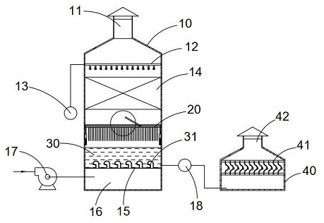
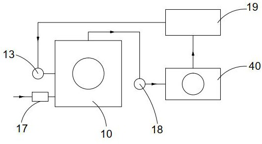
[0045] See attached Figure 1-9 Shown, a kind of odor purifying device comprises:

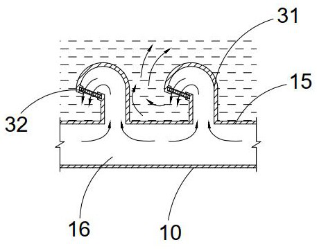
[0046] The first box body 10, the inner bottom of the first box body 10 is separated by the first partition plate 15 to form an air intake chamber 16, the first box body 10 is provided with a second pump body 17, and the second pump body 17 passes through the pipe body and The air intake chamber 16 is in communication, the upper part of the first partition 15 has an air intake pipe body 31 communicating with the bottom air intake chamber 16, and the upper part of the first box body 10 is connected with a first exhaust pipe 11,

[0047] The bottom of the first box body 10 on the top of the first dividing plate 15 is placed with liquid to form the washing layer 30, and the liquid level of the washing layer 30 is higher than the intake pipe body 31,

[0048] Wherein, the air inlet pipe body 31 air outlet ends are bent and set, the air inlet pipe body 31 air outlet direction is set toward the firs...

Embodiment 2

[0069] The further optimization scheme of present embodiment on the basis of embodiment 1 is: see appendix Figure 10-12 As shown, the water discharged in the first tank 10 is sent to the waste water treatment tank 40 through the third pump body 18, the upper part of the waste water treatment tank 40 is provided with a second exhaust pipe 42, and the upper part of the waste water treatment tank 40 is provided with a slow flow Component 41, the slow-flow component 41 includes slow-flow fixing rods 411 arranged on two opposite inner walls of the waste water treatment tank 40, the positions of the two slow-flow fixing rods 411 are corresponding and both are horizontally arranged, and the two slow-flow fixing rods 411 are connected with The slow flow arc plate 412, the middle part of the slow flow arc plate 412 is a vertically arranged plate protruding to one side to form a convex arc surface. Arc-shaped slow-flow sub-plate 413 is arranged. Wastewater treatment tank 40 is filled ...

Embodiment 3

[0073] The further optimization scheme of present embodiment on the basis of embodiment 1 is: see appendix Figure 13 As shown, the air intake chamber 16 is provided with a filter screen 50 arranged horizontally, and the pipe body air inlet of the second pump body 17 is set at the filter screen 50, and the filter screen 50 is provided with a folded The curved guide plate 51 is bent, and the bent part of the upper end of the guide plate 51 is inclined upward to guide the airflow to flow upward. The guide plate 51 is arranged near the air inlet of the air intake chamber 16. The height of the air inlet of the pipe body of the second pump body 17 corresponds to the bending portion at the upper end of the deflector bend plate 51 . Through the filter screen 50 provided in the intake chamber 16, the airflow sent into the interior of the intake chamber 16 can be preliminarily filtered, and the fluff and other floating objects in the filtered airflow can be relatively reduced, and the ...


PUM


Abstract

The invention discloses an odor purification device, and belongs to the field of odor treatment. The device comprises a first box body, the bottom in the first box body is divided by a first partition plate to form an air inlet cavity, a second pump body is arranged outside the first box body and communicates with the air inlet cavity through a pipe body, and an air inlet pipe body is arranged on the upper portion of the first partition plate. The upper portion of the first box body is connected with a first exhaust pipe, the upper portion of the first partition plate is provided with a water washing layer, the air outlet end of the first exhaust pipe is bent, the air outlet of the first exhaust pipe faces the first partition plate, the first exhaust pipe is a square pipe, and the two opposite pipe walls of the air outlet of the first exhaust pipe are provided with inserting grooves corresponding in position. Exhaust plate groups are arranged in the inserting grooves. According to the device, the odor is collected and then treated in a centralized mode, the removal rate of the treated odor reaches 96% or above, the odor divergence rate is reduced, the dust content in the odor is reduced while the odor is treated through a water washing method, and the whole odor treatment process is low in noise, low in cost and high in practicability.

Description

technical field [0001] The invention belongs to the technical field of waste odor treatment, and in particular relates to an odor purification device. Background technique [0002] The descriptions in this section merely provide background information related to the disclosure in this application and may not constitute prior art. [0003] The screening pretreatment of municipal solid waste is the first step in the recycling of urban waste, but a large amount of dust and odor are often emitted during the waste screening process, which seriously affects the surrounding environment and manual work, especially for waste disposal. The environment and air quality near the station or garbage collection point have a great impact, and the garbage will emit a large amount of malodorous substances represented by sulfur and nitrogen compounds during the long-term storage process, which is listed as the second only to noise pollution. The second major pollution, due to its relatively lo...

Claims


Application Information

Patent Timeline
IPC IPC(8): B01D53/84B01D53/38B01D50/00B01D46/10B01D47/06B01D53/18
CPCB01D53/84B01D53/38B01D46/10B01D47/06B01D53/18B01D50/60Y02A50/20
Inventor 金丽美
Owner 宇星环保工程有限公司
Why Eureka
Try Eureka