An automatic marking device for cylindrical NdFeB magnets
What is Al technical title?
Al technical title is built by PatSnap Al team. It summarizes the technical point description of the patent document.
An automatic marking, NdFeB technology, applied in printing devices, packaging automatic control, packaging, etc., can solve the problems of high labor intensity of employees, lower production qualification rate of cylindrical NdFeB magnets, and low marking efficiency.
Active Publication Date: 2021-11-19
NINGBO YUNSHENG +1
View PDF0 Cites 0 Cited by
Summary
Abstract
Description
Claims
Application Information
AI Technical Summary
This helps you quickly interpret patents by identifying the three key elements:
Problems solved by technology
Method used
Benefits of technology
Problems solved by technology
However, the manual single-piece marking method not only has low marking efficiency and high marking cost, it is not suitable for mass production, and the labor intensity of employees is high, and the markings made by different employees are also quite different, so that the final cylindrical NdFeB magnets The consistency is poor. In addition, the marked cylindrical NdFeB magnets need to be packed and transferred to the subsequent magnetization process for magnetization. Therefore, the marked cylindrical NdFeB magnets need to be For packaging, the manual arrangement is still used in the packaging process, that is, after each cylindrical NdFeB magnet is marked, the cylindrical NdFeB magnet needs to be loaded into the receiving hose according to a specific orientation. During this packaging process, it is very easy for employees to reverse the front and rear orientations of the cylindrical NdFeB magnets. Once they are reversed, the actual polarity of the cylindrical NdFeB magnets after subsequent magnetization will be opposite to the marked polarity, and eventually Resulting in a decline in the production pass rate of cylindrical NdFeB magnets
Method used
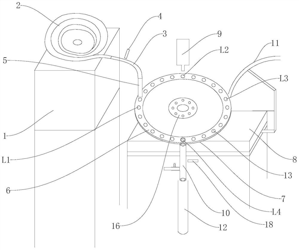
Image
Click on the blue label to locate the original text in one second.
Reading with bidirectional positioning of images and text.
Examples
Embodiment
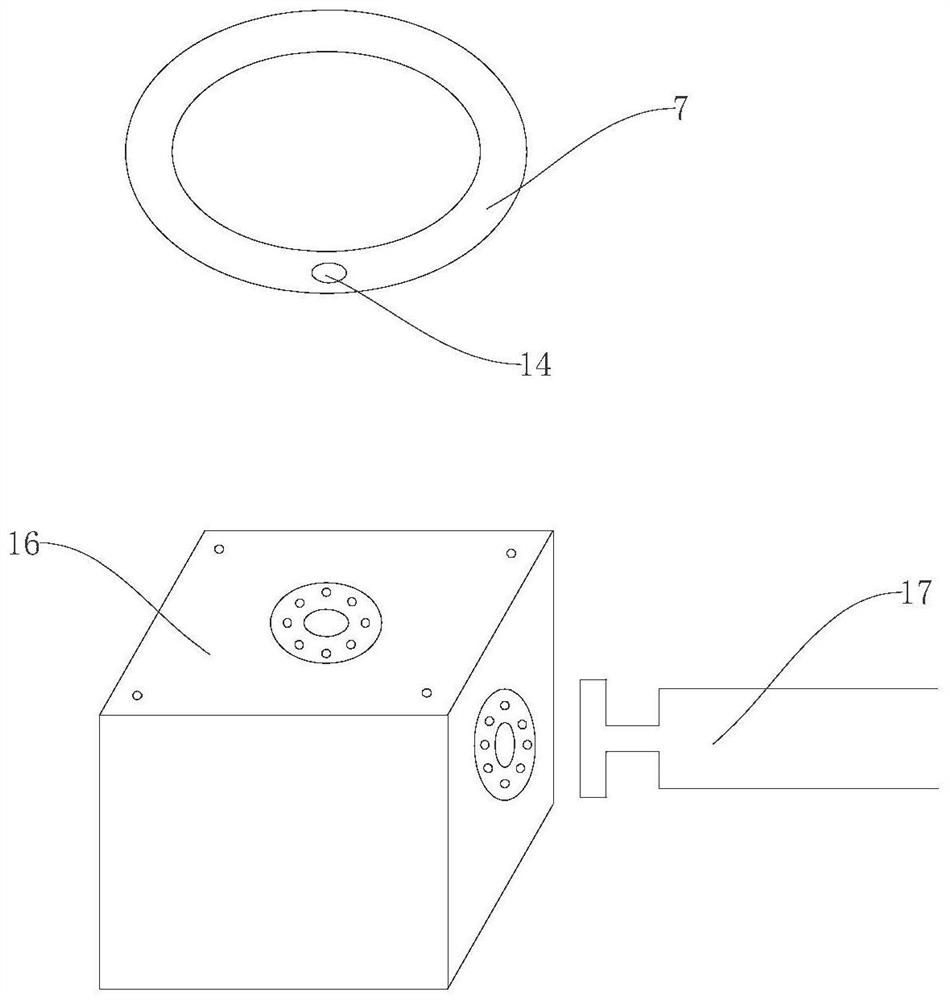
[0013] Example: such as figure 1 and figure 2 As shown, an automatic marking device for cylindrical NdFeB magnets includes a control module, a support table 1, a vibrating feeding tray 2, a feeding hose 3 capable of accommodating a cylindrical NdFeB magnet, and a first optical fiber Sensor 4, guiding channel 5, rotating disk 6, supporting disk 7, workbench 8, driver, inkjet printer 9, feeding pipe 10, air blowing pipe 11 and receiving hose for packing cylindrical NdFeB magnets 12. The control module is respectively connected to the vibrating feeding tray 2, the first optical fiber sensor 4, the driver and the inkjet printer 9, and can control the vibrating feeding tray 2, the driver and the inkjet printer 9 to work together. Station L1, marking station L2, drying station L3 and blanking station L4, the driver is installed on the workbench 8, the rotating disk 6 is installed on the driver, the supporting disk 7 is located below the rotating disk 6, and is fixed on the On the...
PUM
Abstract
The invention discloses an automatic marking device for cylindrical NdFeB magnets, which comprises a support table, a vibrating feeding tray, a feeding hose, a first optical fiber sensor, a guide channel, a rotating disc, a supporting disc, a workbench, a driver, and a spray nozzle. coding machine, feeding pipe, blowing pipe and receiving hose for packaging cylindrical NdFeB magnets; the advantage is that the cylindrical NdFeB magnets can be transported after being erected, so that the existing assembly line can be used Automatic coding marking technology realizes polarity marking, high marking efficiency, low marking cost, suitable for mass production, uniform marking, high consistency of cylindrical NdFeB magnets, low labor intensity of employees, and After marking, the cylindrical NdFeB magnets can be automatically packaged, and the orientation of the cylindrical NdFeB magnets will not be reversed, so as to ensure the actual polarity and marked polarity of the cylindrical NdFeB magnets after subsequent magnetization Similarly, improve the production pass rate of cylindrical NdFeB magnets.
Description
technical field [0001] The invention relates to an automatic marking device, in particular to an automatic marking device for cylindrical neodymium iron boron magnets. Background technique [0002] NdFeB magnets have excellent magnetic properties and high cost performance, and have been widely used in modern industry, electronic technology, information technology, nuclear magnetic resonance, wind power generation, servo motors and new energy vehicles and other fields. At the same time, the demand for NdFeB magnets is also increasing. In order to ensure the demand of NdFeB magnets, it is necessary to improve its production efficiency. Therefore, the current production process of NdFeB magnets has put forward very high requirements. [0003] In order to facilitate the installation of NdFeB magnets by customers in the later stage, NdFeB magnet manufacturers need to mark the polarity on the end face of NdFeB magnets during the production process. For NdFeB magnets of conventio...
Claims
Application Information
Patent Timeline
Application Date:The date an application was filed.
Publication Date:The date a patent or application was officially published.
First Publication Date:The earliest publication date of a patent with the same application number.
Issue Date:Publication date of the patent grant document.
PCT Entry Date:The Entry date of PCT National Phase.
Estimated Expiry Date:The statutory expiry date of a patent right according to the Patent Law, and it is the longest term of protection that the patent right can achieve without the termination of the patent right due to other reasons(Term extension factor has been taken into account ).
Invalid Date:Actual expiry date is based on effective date or publication date of legal transaction data of invalid patent.